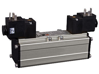
ISO 5599-1 [W60 & W64 Series] Spool & Sleeve and Poppet, Individual Valve Connection
![ISO 5599-1 [W60 & W64 Series]](https://ross-admin-global-us-east.s3.amazonaws.com/production/uploads/series_image/image/2263/W60_dbl_Solenoid_Alm.png)
- Poppet & Spool & Sleeve Options
- Pilot operation provides high shifting force with low power consumption
- Available port sizes include: 1/8”, 1/4”, 3/8”, 1/2”, and 3/4”
- Inlet pressure from vacuum to 150 psig (10 bar)
- Available with Buna-N and Flouroelastomer seals for a wide temperature range
- Single base and manifold base mounting
Directional Control Valves ISO 5599-1 W60 & W64 Series Product Overview
The ROSS® ISO 5599-1 valves W60 Series are base mounted spool and sleeve valves that conform to the ISO standards 5599-1 mounting interface. These ISO Size 1, 2, and 3 valves are available as, 2- and 3-position, 5-ported 4-way valves. Solenoid pilot options include a non-locking manual override, and either internal or external pilot supply.
Please refer to the side and below for links to easily navigate and download ROSS Controls Directional Control Valves ISO 5599-1 W60 & W64 Series catalogs, installation instructions, and technical data. Additionally, you have the option to filter through all available options to discover Directional Control Valves ISO 5599-1 W60 & W64 Series variant that meets your requirements.
loading...
loading...
Product Overview
The ROSS Controls W60 and W64 Series () are base-mounted directional control valves conforming to the ISO 5599-1 mounting interface standard. Available in ISO Size 1, 2, and 3 with port sizes from 1/8" to 3/4", these valves address a wide range of pneumatic circuit flow requirements in general industrial, process, and high-temperature environments.
The W60 Series uses spool and sleeve construction. The precision stainless steel spool operates within a machined aluminum sleeve with minimal diametral clearance and no elastomeric dynamic seals on the spool itself. This eliminates seal wear, seal extrusion, and seal degradation as failure mechanisms, making the W60 the preferred choice for high-cycle, long-service applications where minimizing unplanned maintenance intervals is the priority. Valve bodies are machined from bar stock aluminum, providing superior wall thickness consistency compared to cast alternatives.
The W64 Series uses poppet valve technology that is specifically engineered for contaminated-air environments and high-temperature service. The poppet seals against a precision seat by spring force, creating a positive shut-off that is mechanically tolerant of ingested particulate. High-velocity airflow across the poppet seat during each cycle creates a self-cleaning action that continuously removes debris from the sealing interface. This makes the W64 the correct choice for applications in concrete batching, mining, foundry operations, outdoor installations, and anywhere that filter maintenance cannot be guaranteed.
Both series are available with solenoid pilot (electrical) and pressure-controlled (pneumatic pilot) actuation. Solenoid valves use a low-power pilot coil to direct pneumatic pressure to shift the main valve element, providing high shifting force from a compact, energy-efficient solenoid. All solenoid models include non-locking manual overrides and EN 175301-803 Form A electrical connectors. Temperature seal options extend the W64 Series to 220 F (105 C) ambient and media using fluorocarbon seals in place of the standard Buna-N.
Key Engineering Features
- Dual Construction Options - Spool and Sleeve (W60) or Poppet (W64) - W60 spool and sleeve construction provides consistent sealing performance and low internal friction for high-cycle clean-air applications. W64 poppet construction provides contamination-resistant positive shut-off with self-cleaning action for harsh environments where air quality cannot be controlled.
- W64 High-Temperature Fluorocarbon Seal Option - W64 poppet valves are available with fluorocarbon (Viton) seals rated to 220 F (105 C) ambient and media temperature, making them directly applicable to drying systems, heat-treating equipment, hot stamping, and other elevated-temperature processes where standard Buna-N seals would degrade.
- Pilot Operation for High Shifting Force at Low Power - Both W60 and W64 solenoid pilot valves use pneumatic amplification, with a small solenoid coil directing pilot air to generate the force required to shift the main valve element. This provides reliable shifting at 6 watts DC without the high inrush current of direct-acting solenoid designs.
- Bar Stock Aluminum Body Construction (W60 and W64) - Valve bodies are machined from bar stock aluminum rather than die-cast, ensuring consistent wall thickness, elimination of casting voids, and superior dimensional accuracy for the precision bores that define spool clearances and port geometry.
- W60 - No Dynamic Seals on Main Spool - The W60 spool operates on a fluid film within the sleeve clearance with no elastomeric dynamic seals on the spool element itself, eliminating seal wear as a service life determinant and providing consistent internal leakage performance across millions of cycles.
- W64 Self-Cleaning Poppet Action - High-velocity airflow across the poppet seat during each actuation cycle displaces accumulated particulate from the sealing interface, making the W64 tolerant of contaminated air supplies without requiring ultra-fine filtration upstream.
- ISO Size 1, 2, and 3 Availability for Flow Scalability - Three ISO sizes provide a scalable flow range within the same standard: Size 1 at Cv 0.8-1.0, Size 2 at Cv 1.9-2.0, and Size 3 at Cv 3.8-4.0. This allows engineers to right-size valve flow capacity to actuator requirements across diverse machine designs while using common sub-base and manifold infrastructure.
- Port Sizes from 1/8" to 3/4" - Sub-bases for ISO 5599-1 Size 1 through Size 3 accommodate port sizes from 1/8" up to 3/4", allowing direct connection to standard pneumatic tubing and pipe sizes without reducing fittings that would create flow restriction.
- Solenoid Pilot and Pressure-Controlled Actuation Options - Both electrical solenoid pilot and pneumatic pressure-controlled actuation are available. Pressure-controlled variants are required for intrinsically safe areas, electrically classified zones, and applications where electrical infrastructure is unavailable or undesirable.
- 5/2 and 5/3 Functions with Full Center Position Selection - Both W60 and W64 provide 5/2 single and double solenoid functions plus 5/3 double solenoid with closed, power, or open center positions, covering virtually all double-acting cylinder and rotary actuator control requirements.
- Non-Locking Manual Override Standard on Solenoid Models - All solenoid pilot W60 and W64 valves include a non-locking manual override as standard, allowing forced valve actuation during system commissioning and fault diagnosis without requiring electrical power or disassembly.
- EN 175301-803 Form A Electrical Connection - The DIN EN 175301-803 Form A (standard DIN) connector is standard on all W60 and W64 solenoid valves, providing compatibility with the widest range of prewired and field-wired connector assemblies available from multiple connector suppliers.
- UL Listed and IP65 Rated Solenoids - W60 and W64 solenoid enclosures carry UL listing for the US and Canadian market and IP65 environmental protection, confirming suitability for washdown environments and applications with exposure to water jets or heavy dust loading.
Technical Specifications
General Specifications
| Parameter | Specification |
| Valve Series | W60 (Spool and Sleeve); W64 (Poppet) |
| Valve Standard | ISO 5599-1 |
| Valve Type | Directional Control |
| Construction | W60: Spool and Sleeve; W64: Poppet |
| Actuation | Electrical - Solenoid Pilot Controlled; Pneumatic - Pressure Controlled |
| Valve Functions | 5/2 Single Solenoid, 5/2 Double Solenoid, 5/3 Double Solenoid (Closed/Power/Open Center), 5/2 Single Pilot (Pneumatic), 5/2 Double Pilot (Pneumatic), 5/3 Double Pilot (Pneumatic) |
| ISO Sizes Available | Size 1, Size 2, Size 3 |
| Available Port Sizes | 1/8", 1/4", 3/8", 1/2", 3/4" (at sub-base level) |
| Mounting | Base Mounted - Single Sub-Base or Manifold Base |
| Operating Pressure - W60 Spool and Sleeve | Vacuum to 150 psig (Vacuum to 10 bar) |
| Operating Pressure - W64 Poppet | 30 to 150 psig (2 to 10 bar) |
| Pilot Supply Minimum - Solenoid Pilot | Must be equal to or greater than inlet pressure |
| Pilot Supply Minimum - Pressure Controlled | Must be equal to or greater than inlet pressure |
| Fluid Media | Filtered compressed air |
| Connection Type | EN 175301-803 Form A (DIN connector) |
| Manual Override | Non-locking (standard on solenoid models) |
| Valve Body Material | Bar Stock Aluminum |
| Spool/Poppet Material - W60 | Stainless Steel |
| Spool/Poppet Material - W64 | Aluminum and Stainless Steel |
| Standard Seal Material | Buna-N (Nitrile Rubber) |
| High-Temperature Seal Option (W64) | Fluorocarbon (Viton) |
| Thread Options | NPT; G (BSPP) |
Temperature Ratings
W60 spool and sleeve valves cover standard temperature range. W64 poppet valves offer both standard and high-temperature configurations. High-temperature W64 variants require fluorocarbon seals.
| Configuration | Ambient Temperature | Media Temperature |
| W60 Spool and Sleeve - Solenoid Pilot | 40 to 120 F (4 to 50 C) | 40 to 175 F (4 to 80 C) |
| W60 Spool and Sleeve - Pressure Controlled | 40 to 175 F (4 to 80 C) | 40 to 175 F (4 to 80 C) |
| W64 Poppet - Standard (Buna-N) | 40 to 175 F (4 to 80 C) | 40 to 175 F (4 to 80 C) |
| W64 Poppet - High Temperature (Fluorocarbon) | 40 to 220 F (4 to 105 C) | 40 to 220 F (4 to 105 C) |
Electrical Data (Solenoid Pilot Valves)
All solenoid valves are rated for continuous duty. Solenoid enclosures are IP65. UL listed for US and Canadian markets.
| Voltage | Power Consumption |
| 24 VDC | 5.8 watts nominal; 6.5 watts maximum (each solenoid) |
| 110/120 VAC, 50/60 Hz | 5.8 watts nominal; 6.5 watts maximum (each solenoid) |
| 230/240 VAC, 50/60 Hz | Contact ROSS Controls |
Flow Performance Data
Average Cv, flow capacity in Nl/min, and representative dimensions per ISO size for W60 spool and sleeve and W64 poppet valve series.
| Series | ISO Size | Avg Cv | Flow Nl/min | Body Length | Body Height |
| W60 Spool and Sleeve | 1 | 0.8 | 790 | 1.7 in (42 mm) | 4.4 in (112 mm) |
| W60 Spool and Sleeve | 2 | 1.9 | 1,900 | 2.1 in (54 mm) | 4.7 in (119 mm) |
| W60 Spool and Sleeve | 3 | 3.8 | 3,700 | 2.6 in (65 mm) | 4.9 in (124 mm) |
| W64 Poppet | 1 | 1.0 | 980 | 1.7 in (42 mm) | 4.4 in (112 mm) |
| W64 Poppet | 2 | 2.0 | 2,000 | 2.1 in (54 mm) | 2.1 in (54 mm) |
| W64 Poppet | 3 | 4.0 | 3,900 | 2.6 in (65 mm) | 2.3 in (59 mm) |
Response Time Formula: Response Time (ms) = M + (F x V), where M is the minimum response constant, F is the fill or exhaust factor, and V is the downstream volume in cubic inches. M and F values vary by valve size and function. For W60 Size 1 single solenoid: M = 29 ms. For W60 Size 3: M = 51 ms. Refer to the ROSS ISO 5599-1 catalog for complete M and F tables.
Certifications & Compliance
| Certification/Standard | Detail |
| ISO 5599-1 Compliance | Full conformance to ISO 5599-1 mounting interface standard, specifying port locations, bolt pattern, orifice dimensions, and pilot passage geometry for worldwide valve and manifold interchangeability. |
| UL Listing | UL listed solenoid valves for the US and Canadian markets, confirming compliance with North American electrical safety standards for industrial control equipment. |
| Declaration of Conformity (CE) | CE marking per applicable EU directives confirming compliance with European health, safety, and environmental requirements for the industrial machinery market. |
| IP65 Enclosure Protection | IP65 per IEC 60529, providing dust-tight protection and resistance to low-pressure water jets. Confirms suitability for washdown environments and applications with exposure to heavy dust loading or water spray. |
| CRN Certification | Canadian Registration Number (CRN) certification for applicable pressure-containing configurations, satisfying provincial boiler and pressure vessel regulations across Canadian provinces. |
Typical Applications & Industries
General Factory Automation and Assembly
- Pick-and-place, transfer, and parts feeding systems using double-acting cylinders in standard temperature factory environments where W60 spool and sleeve longevity minimizes preventive maintenance intervals.
- Assembly machine clamping circuits and fixturing for welding, pressing, and joining processes requiring reliable 5/2 or 5/3 directional control of rod-style and guided cylinders.
- Conveyor diverters, gate controls, and product routing systems in material handling that operate continuously at moderate cycle rates and require consistent valve response over extended service periods.
- Palletizer and depalletizer actuator circuits where ISO 5599-1 manifold assemblies consolidate pneumatic distribution for multi-axis layer-building sequences.
Harsh and Contaminated Environments (W64 Poppet)
- Concrete batching and precast manufacturing where airborne cement dust rapidly clogs inline filters and bypasses standard filtration, requiring the self-cleaning poppet design of the W64 to maintain reliable shifting.
- Foundry and metal casting operations where fine metal particles and sand are present in the ambient air, making poppet contamination tolerance the primary design requirement for pneumatic control valves.
- Mining, quarry, and aggregate processing equipment where dust loading and outdoor exposure eliminate the option of maintaining filter elements at the intervals required for spool valve service.
- Agricultural equipment and food ingredient processing where product dust or organic particulate is consistently present in the operating environment around pneumatic components.
High-Temperature Process Applications (W64 Fluorocarbon)
- Industrial drying tunnels and ovens where ambient temperatures around the pneumatic components routinely exceed 175 F (80 C) and standard Buna-N seals would harden, crack, and lose sealing integrity.
- Thermoset molding and heat-curing equipment where mold tooling pneumatics operate in sustained elevated-temperature environments during production cycles.
- Hot stamping, heat-treating, and metal forming equipment where press and die actuation pneumatics are located in proximity to heated tooling and workpiece material.
- Textile drying and processing lines where high ambient temperatures around drying chambers require fluorocarbon-sealed valves for reliable long-term operation.
Packaging, Food and Beverage, and Process Industries
- Primary and secondary packaging lines using 5/3 center position valves to hold actuators in position during product metering, filling, or alignment phases of the machine cycle.
- Pressure-controlled (pneumatic pilot) valve applications in explosion-proof or intrinsically safe areas within food processing facilities where eliminating solenoid electrical components is required by the area classification.
- Dairy, beverage, and liquid food filling lines where manifold base mounting consolidates valve connections and reduces inline plumbing joints in the machine frame.
- Pharmaceutical manufacturing tablet presses, blister packaging, and counting equipment where ISO 5599-1 interchangeability simplifies global spare parts standardization across multiple plant locations.
Ordering and Model Number Configuration
The W60 and W64 Series model number encodes the series designation, configuration and function code, revision level, ISO size, voltage/solenoid type, and temperature class. Understanding this structure allows engineers to specify exact configurations and decode installed valve identification plates.
|
Model Number Example: W 6 0 7 6 B 3 4 0 1 W
W Series prefix 60 Series: 60 = W60 Spool and Sleeve; 64 = W64 Poppet 7 Actuation: 7 = Solenoid Pilot; 5 = Pressure Controlled (Pneumatic) 6 Function/Positions indicator B Revision Level 3 ISO Size: 1 = Size 1; 2 = Size 2; 3 = Size 3 4 Function code: single/double solenoid or pilot 01 Configuration: NC/NO, center position W Voltage: W = 24 VDC; Z = 110/120 VAC; Y = 230/240 VAC
W64 High-Temperature Selection: Standard Temperature = Buna-N seals (ambient to 175 F / 80 C) High Temperature = Fluorocarbon seals (ambient to 220 F / 105 C)
Typical Model Examples: W6076B3401W W60, Solenoid Pilot, Size 2, 5/2 Single Sol, 24 VDC W6077B2401Z W60, Solenoid Pilot, Size 1, 5/3 Double Sol, 120 VAC W6456B3417 W64, Pneumatic Pilot, Size 2, 5/2 Double Pilot W6456B4412 W64 High Temp, Pneumatic Pilot, Size 3, Fluorocarbon |
W60 valves use spool and sleeve construction and are suitable for vacuum through 150 psig service. W64 valves use poppet construction and require a minimum of 30 psig inlet pressure.
High-temperature W64 configurations use fluorocarbon seals for service to 220 F (105 C). Standard W64 and all W60 valves use Buna-N seals rated to 175 F (80 C) media temperature.
Voltage codes: W = 24 VDC, Z = 110/120 VAC, Y = 230/240 VAC. For pressure-controlled (pneumatic pilot) valves, no voltage code is used.
Port size is specified at the sub-base level. Sub-bases for Size 1 accommodate 1/8" to 3/8" ports; Size 2 handles 3/8" to 1/2"; Size 3 accommodates 1/2" to 3/4". Select sub-base port size to match the system piping or tubing size without restricting flow.
For G (BSPP) threads, specify the G-thread sub-base part number. Valve body model numbers are the same for NPT and G-thread installations; thread type is selected at the sub-base level.
Flow Capacity and Dimensions by ISO Size
| Series | ISO Size | Avg Cv | Body Length | Solenoid Width | Pneumatic Width | Weight (Solenoid, lb/kg) |
| W60 | 1 | 0.8 | 1.7 in (42 mm) | 6.7 in (170 mm) | 4.4 in (112 mm) | 1.8 / 0.9 |
| W60 | 2 | 1.9 | 2.1 in (54 mm) | 6.2 in (158 mm) | 5.3 in (135 mm) | 2.3 / 1.1 |
| W60 | 3 | 3.8 | 2.6 in (65 mm) | 6.6 in (168 mm) | 6.4 in (163 mm) | 3.9 / 1.8 |
| W64 | 1 | 1.0 | 1.7 in (42 mm) | N/A | 4.4 in (112 mm) | N/A |
| W64 | 2 | 2.0 | 2.1 in (54 mm) | N/A | 5.1 in (130 mm) | 2.3 / 1.0 |
| W64 | 3 | 4.0 | 2.6 in (65 mm) | 6.8 in (173 mm) | 6.4 in (163 mm) | 3.3 / 1.5 |
Accessories
Single Sub-Bases
Individual sub-bases provide dedicated port connections at each ISO size for standalone valve installations. Sub-base port sizes span 1/8" to 3/8" for Size 1, 3/8" to 1/2" for Size 2, and 1/2" to 3/4" for Size 3. Available in NPT and G (BSPP) thread forms. Port size should be matched to system piping size to avoid flow restriction that would reduce actuator speed.
Multi-Station Manifold Bases
Gang manifold bases share common supply and exhaust passages across all mounted valve stations, reducing external plumbing connections. Manifold bases for ISO 5599-1 are available in multi-station configurations with common supply and exhaust ports sized to the manifold capacity. End station kits complete the manifold assembly with the required end seals and port plugs.
Interposed Flow Controls
Interposed meter-out flow controls mount between the valve body and sub-base to provide independent speed control for each actuator port without external needle valves in the actuator circuit. Flow control units are available for each ISO size.
Interposed Supply and Exhaust Modules
Intermediate modules allow individual manifold stations to use independent supply or exhaust pressure zones. These are inserted between specific valve stations on the manifold rail without requiring separate manifold assemblies for different circuit pressure zones.
EN 175301-803 Electrical Connectors
Pre-wired DIN EN 175301-803 Form A connector assemblies with 2-meter (6.5-foot) cable leads are available in standard and LED-indicator versions for 24 VDC, 120 VAC, and 230 VAC. Lighted connectors provide visual solenoid-energized confirmation at the valve body without requiring test equipment. Both cable grip and 1/2" NPT conduit entry versions are available.
Exhaust Silencers
Silencers reduce exhaust noise at valve sub-base and manifold exhaust ports. Port sizes from 1/8" through 3/4" are available. Silencer Cv must equal or exceed the valve exhaust capacity to prevent back pressure from degrading valve response. Contaminated silencers must be replaced at regular intervals.
Warning: Silencer flow capacity must equal or exceed valve exhaust Cv. Back pressure created by undersized or contaminated silencers opposes pilot pressure during spool shifting and can cause incomplete valve actuation, particularly at low operating pressures.
Related Products & Accessories
- ISO 15407-1 W66 Series (Series 240) - Compact ISO 15407-1 spool and sleeve valves in ISO Size 01 (26 mm) and Size 02 (18 mm) with individual 4-pin M12 connections for lower-flow applications. https://www.rosscontrols.com/en/series/240-iso-15407-1-w66-series
- ISO 15407-2 W66 Series (Series 241) - ISO 15407-2 spool and sleeve valves in Size 01 and Size 02 with integrated plug-together manifold electrical connections. https://www.rosscontrols.com/en/series/241-iso-15407-2-w66-series
- ISO 5599-2 W65 Series (Series 243) - ISO 5599-2 spool and sleeve valves in ISO Size 1, 2, and 3 with integrated plug-together manifold electrical connections and automotive connector options. https://www.rosscontrols.com/en/series/243-iso-5599-2-w65-series
- Exhaust Silencers - Aluminum exhaust silencers for 1/8" through 3/4" port sizes for installation at W60 and W64 sub-base and manifold exhaust ports. https://www.rosscontrols.com/en/series/90-silencers
- Electrical Connectors - DIN EN 175301-803 Form A connector assemblies and prewired cables for W60 solenoid valves, available with and without LED indicator lights. https://www.rosscontrols.com/en/series/91-electrical-connectors
- Lockout Valves (L-O-X Energy Isolation) - ROSS L-O-X lockout valves for safe upstream energy isolation of W60 and W64 valve manifold assemblies during maintenance per OSHA lockout/tagout requirements. https://www.rosscontrols.com/en/series/1287-lockout-valves-15-series
Frequently Asked Questions (FAQ)
Q: When should a design engineer specify W60 spool and sleeve versus W64 poppet for an ISO 5599-1 application?
A: Specify W60 spool and sleeve for clean, filtered-air applications at standard temperatures where high cycle rates and long service life are the primary drivers. The absence of dynamic seals on the spool makes W60 the best choice when preventive maintenance intervals must be maximized. Specify W64 poppet for applications where air quality cannot be guaranteed to meet 40-micron filtration requirements, where contamination is ingested despite filtration, or where ambient or media temperatures exceed 175 F (80 C). The W64's self-cleaning poppet seat and fluorocarbon seal option directly address these failure mechanisms.
Q: What is the operating pressure range for each construction type?
A: W60 spool and sleeve valves operate from full vacuum through 150 psig (10 bar). W64 poppet valves require a minimum inlet pressure of 30 psig (2 bar) because the poppet relies on a spring force that must be overcome by pneumatic pressure to open. The W64 does not support vacuum service because the poppet seal is pushed closed by both the spring and atmospheric pressure differential. For vacuum applications, the W60 or the W66 Series must be specified.
Q: What are the temperature limits for the standard Buna-N seal option?
A: Standard Buna-N seals on both W60 and W64 valves support a media temperature range of 40 to 175 F (4 to 80 C). For W60 solenoid pilot models, the ambient temperature limit is 40 to 120 F (4 to 50 C) due to the solenoid coil rating. W60 pressure-controlled models extend ambient to 175 F. Standard W64 valves (both solenoid and pneumatic actuation) support ambient to 175 F with Buna-N seals.
Q: How do I select the correct sub-base port size for a given ISO size valve?
A: Sub-base port sizes are matched to valve ISO size: ISO Size 1 sub-bases are available with 1/8" to 3/8" ports, Size 2 with 3/8" to 1/2" ports, and Size 3 with 1/2" to 3/4" ports. Select a port size that matches the downstream tubing or pipe size to avoid creating a flow restriction at the sub-base connection. In most cases, selecting the largest available port size for the ISO size provides the best flow coefficient and avoids velocity-induced pressure drop at the port threads.
Q: What is the difference between 5/2 single solenoid and 5/2 double solenoid functions?
A: A 5/2 single solenoid valve has one solenoid that shifts the spool against a spring return. When the solenoid is energized, the valve shifts to one state; when de-energized, the spring returns the spool to the normal position. A 5/2 double solenoid valve has one solenoid on each end of the spool with no return spring. The valve remains in its last commanded state when both solenoids are de-energized (memory position), until the opposite solenoid is energized to shift it. Double solenoid valves are used where the actuator must remain in position if power is interrupted and a loss-of-power return stroke would cause a safety or process hazard.
Q: Are pressure-controlled (pneumatic pilot) W60 and W64 valves available?
A: Yes. Both W60 and W64 are available with pressure-controlled (pneumatic pilot) actuation, eliminating the solenoid coil entirely. Pneumatic pilot valves are required for intrinsically safe areas classified as hazardous by the NEC, ATEX, or IECEx standards where electrical components cannot be used, and for applications where no electrical supply is available. The pilot signal is a pneumatic pressure applied to the pilot port. Single and double pilot configurations are available for 5/2 and 5/3 functions.
Q: What is the IP rating of the W60 and W64 solenoid enclosures?
A: W60 and W64 solenoid enclosures carry an IP65 protection rating per IEC 60529. IP65 is dust-tight and protects against low-pressure water jets, making these valves suitable for washdown environments in food and beverage processing, dairy facilities, and outdoor machine installations exposed to rain.
Q: Can W60 and W64 valves be used with an air line lubricator?
A: Air line lubrication is not required for W60 or W64 valves under standard conditions. If a lubricator is already present in the system, use petroleum-based lubricant at ISO 32 viscosity or lighter at approximately one drop per minute. Avoid phosphate-ester-based lubricants, which are incompatible with Buna-N seals. Note that if lubricated air is introduced to a system that has run unlubricated, the oil will wash any residual lubrication from spool surfaces during the transition, which can temporarily increase friction before stabilizing.
Q: What standard electrical connector is used with W60 solenoid valves?
A: W60 and W64 solenoid valves use the EN 175301-803 Form A (commonly known as the standard DIN connector) as the standard electrical connection. This is the most widely used industrial solenoid connector worldwide, with prewired cable assemblies and field-wirable connectors available from ROSS Controls and numerous connector manufacturers. ROSS offers 2-meter prewired assemblies with standard and LED-indicator versions in 24 VDC, 120 VAC, and 230 VAC.
Q: Are manifold assemblies available for the W60 and W64 Series?
A: Yes. Multi-station manifold bases conforming to ISO 5599-1 are available for Size 1, 2, and 3 W60 and W64 valves. Manifold bases share common supply and exhaust passages, reducing the number of external plumbing connections. Intermediate isolation plates, blank stations, end station kits, and flow control modules are available as manifold accessories. Contact ROSS Controls for manifold assembly configuration and dimensioned drawings.
Q: Can W60 spool valves and W64 poppet valves be mounted on the same ISO 5599-1 manifold?
A: Yes, provided both are the same ISO size. ISO 5599-1 specifies a common mounting interface that is identical for both spool and poppet valve body styles at the same ISO size. W60 and W64 valves with the same ISO size designation share the same bolt pattern, port locations, and sub-base or manifold interface dimensions. This allows a manifold to mix spool and poppet valves at different stations if circuit requirements for contamination tolerance or flow characteristics vary by circuit.
Q: How does the response time formula apply to actuator cycle time calculations?
A: Response time uses the formula: Response Time (ms) = M + (F x V), where M is the minimum response time constant, F is the fill or exhaust factor for the specific valve function and size, and V is the downstream volume in cubic inches to be filled or exhausted. For W60 Size 1 single solenoid valves, M = 29 ms. For W60 Size 3, M = 51 ms. These values are used to calculate actuator stroke time from the moment the solenoid is energized to the moment sufficient pressure builds or drops in the actuator to complete the desired motion. Complete M and F tables are published in the ROSS ISO 5599-1 catalog.
Q: What is the expected service life of the W60 spool and sleeve valve?
A: The W60 spool and sleeve design is rated for tens of millions of cycles when operated with clean filtered air within the rated pressure and temperature envelope. The absence of dynamic elastomeric seals on the main spool means there is no conventional seal wear mechanism. The primary service life determinant is contamination: maintaining the recommended 40-micron upstream filtration is the single most important maintenance practice for maximizing W60 valve service life. Actual service life in specific applications depends on cycle rate, operating pressure, temperature, and air quality.
Installation & Maintenance Guidelines
- Confirm that the valve sub-base or manifold surface is clean and flat before installing the valve. ISO 5599-1 specifies maximum allowable flatness deviation for the mounting surface. Surface irregularities that exceed this tolerance allow the base gasket to bridge a gap and permit leakage between port passages at the valve-to-base interface.
- Install base gaskets or O-ring seals before mounting the valve onto the sub-base or manifold. Inspect gasket condition before every valve installation and replace any gasket that shows cuts, permanent compression set, or deformation. A damaged gasket cannot maintain the pressure differential between adjacent ports on the ISO 5599-1 mounting face.
- Torque all valve mounting screws to the specification in the ROSS W60 or W64 installation instructions. The mounting screw torque must be sufficient to compress the base gasket to the designed sealing interference without distorting the valve body. Over-torquing thin-walled valve bodies can introduce bending stress that affects spool or poppet clearance and increases internal leakage.
- Supply filtered compressed air at a minimum of 40-micron filtration to all W60 sub-base inlet ports. W64 poppet valves are more tolerant of contamination by design, but the same filtration standard reduces wear on pilot components in both series. Water separators should be installed upstream to prevent condensate from entering valve internal passages.
- For W64 poppet valves, confirm that inlet pressure is at or above 30 psig (2 bar) before commissioning. Operating below minimum pressure will result in the poppet failing to open fully on each actuation cycle, producing reduced Cv and incomplete actuator stroke. This symptom is easily misdiagnosed as a downstream component failure.
- For W60 solenoid pilot valves with a 40 to 120 F (4 to 50 C) ambient limit, verify that the installation location does not experience ambient temperatures above 120 F. If the valve is mounted near a heat source such as an oven, furnace, or heated press, measure the actual ambient at the valve body location under production conditions before finalizing the installation position.
- When specifying W64 valves for high-temperature service, confirm that fluorocarbon seals are specified in the model number. Standard W64 valves ship with Buna-N seals rated to 175 F. High-temperature fluorocarbon versions are separate model configurations and must be explicitly specified; they are not field-convertible from standard seal versions.
- Assemble the EN 175301-803 Form A electrical connector onto the solenoid body with the connector fully seated and the retaining screw tightened. Partial connector seating or loose retaining screws are the leading cause of intermittent solenoid faults in the field. Test for a positive mechanical click or full engagement before routing the cable.
- Confirm that the DIN connector cable entry is oriented away from potential water or oil drip paths before final installation. Although the IP65 solenoid enclosure resists water jets, sustained water pooling at the cable entry gasket can cause accelerated seal deterioration and eventual moisture ingress.
- For pressure-controlled (pneumatic pilot) W60 or W64 valves, connect the pilot signal line to the dedicated pilot port on the sub-base. The pilot pressure must equal or exceed the inlet supply pressure for reliable shifting. If pilot pressure is less than inlet pressure, the differential force acting across the valve element can prevent the pilot signal from completing the shift, resulting in partial or failed actuation.
- When installing valves on a multi-station manifold, confirm that the supply and exhaust port plug arrangement matches the intended circuit. Manifolds with common supply and exhaust have these ports available at one or both ends; unused end ports must be plugged to prevent unintended supply or exhaust connections from open manifold passages.
- After initial installation, cycle each valve 10 to 20 times under operating pressure before recording baseline performance. Initial cycling seats the base gaskets and distributes residual assembly lubricants from the spool or poppet bores to their operating clearances. Some initial variation in response time during this break-in period is normal.
- For outdoor or low-temperature installations where ambient temperatures approach or fall below 40 F (4 C), ensure that the compressed air supply has a dew point below the minimum ambient temperature. Condensation or ice formation within the valve body can lock a spool in position or prevent a poppet from seating fully, causing air bypassing and unpredictable actuator behavior.
- When replacing a valve in service, document the model number from the valve nameplate before removal. The ISO 5599-1 standard defines the mounting interface, but valve performance characteristics such as Cv, center position, and seal material are encoded in the model number. Installing a replacement with different performance parameters can change actuator speed, holding force, or fail-safe behavior from the original design intent.
Warranty & Global Support
ROSS Controls provides a one-year warranty on all products, covering defects in material and workmanship from date of purchase.
Global technical support is available through ROSS Controls offices in the USA (headquarters in Ferndale, Michigan), Canada, Brazil, Germany, France, United Kingdom, India, China, and Japan.
Contact ROSS Controls USA Customer Service at (800) GET-ROSS (800-438-7677) or Technical Service at (888) TEK-ROSS (888-835-7677). Visit rosscontrols.com for product configuration, CAD model downloads, and distributor locator services.
For complete technical data including dimensional drawings, catalog download, response time constants, and manifold assembly configuration, visit the ROSS Controls ISO 5599-1 W60 and W64 Series product page at rosscontrols.com.
Download Catalog: https://www.rosscontrols.com/en/series/242-iso-5599-1-w60-w64-series
Download Documents
ISO 5599-1 [W60 & W64 Series]