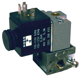
Base Mounted Spool Valves [W14 Series] 3/2 Single Direct Solenoid Valves
![Base Mounted Spool Valves [W14 Series]](https://ross-admin-global-us-east.s3.amazonaws.com/production/uploads/series_image/image/2244/W14_Series_Miniature_Valves.png)
- 3/2 base mounted valve
- Manual override - flush; metal locking, or non-locking
- Indicator light option
W14 Series Base Mounted Poppet Valves Product Overview
Solenoid pilot valves provide reliable pilot control for various pneumatically actuated devices. They are positive sealing and self-compensating for wear with perpendicular poppet face seals. They have consistent actuation over the life of the valve and provide strong shifting forces with low power consumption.
Please refer to the side and below for links to easily navigate and download ROSS Controls W14 Series Base Mounted Poppet Valves catalogs, installation instructions, and technical data. Additionally, you have the option to filter through all available options to discover the ideal W14 Series Base Mounted Poppet Valves variant that meets your requirements.
loading...
loading...
Product Overview
The ROSS Controls W14 Series is a family of miniature base-mounted 3-way, 2-position (3/2) directional control valves using proven poppet construction for applications requiring reliable solenoid pilot control and direct actuation of small pneumatic loads. Available in normally closed function with spring return, the W14 Series operates from vacuum through 150 psig (10 bar) with a flow coefficient of Cv 0.1, positioning these valves as a versatile miniature pilot source and small-actuator direct control valve for industrial automation, OEM machinery, and laboratory instrumentation.
The W14 designation identifies this product within the ROSS miniature poppet valve family. The base-mounted (sub-base mounted) installation architecture differs fundamentally from inline mounting: the valve body drops onto a mating sub-base that provides all external air connections through threaded ports, while the interface between valve body and sub-base uses O-ring face seals rather than pipe-thread connections. This architecture eliminates the need to plumb directly to the valve body, simplifies replacement by allowing the valve to be removed and installed without disconnecting any pneumatic lines, and supports multi-valve manifold assemblies from a single sub-base manifold body.
Poppet construction with perpendicular face seals provides positive sealing with self-compensating wear characteristics, delivering consistent actuation forces and sealing performance over the valve's service life without the sliding spool friction and wear-induced leakage that characterize traditional spool-in-bore designs. Three voltage options cover the primary industrial control voltage spectrum: 24 VDC for PLC-based systems, 110/120 VAC 50/60 Hz for North American installations, and 230 VAC 50/60 Hz for international markets.
Two manual override configurations, locking and non-locking, provide circuit commissioning and emergency control flexibility. An optional indicator light variant provides visual solenoid-energized confirmation directly at the valve, reducing diagnostic time during commissioning and fault-finding. All W14 catalog variants use EN 175301-803 Form A (formerly DIN 43650 Form A) quick-disconnect electrical connectors for fast, standardized coil wiring in field installations.
Key Engineering Features
- Perpendicular Poppet Face Seals - The poppet geometry with perpendicular face seals provides positive sealing across the rated pressure range from vacuum to 150 psig, while self-compensating wear characteristics adjust seal contact geometry as seals wear, maintaining leak-tight performance without the progressive bypass degradation of sliding spool designs.
- Consistent Actuation Over Valve Life - The poppet construction generates strong, consistent shifting forces throughout the valve's operational life because the solenoid acts against a defined spring return load rather than a variable spool friction force that increases as bore tolerances loosen with wear and contamination.
- Base Mounted Sub-Base Architecture - Base mounting to the 516B91 sub-base or multi-station manifold assemblies allows pneumatic connections to remain undisturbed during valve replacement, reduces pipe-to-valve leak points, enables compact multi-valve mounting configurations, and provides structural mechanical support to the valve body independent of tubing connections.
- Three Voltage Options: 24 VDC, 110/120 VAC, 230 VAC - Full voltage coverage from DC process control systems through North American and international AC power standards allows a single valve series to specify across diverse machine architectures and global markets without requiring regional product variants or wiring adapters.
- EN 175301-803 Form A Connector - The industry-standard DIN 43650 Form A quick-disconnect coil connector is universally available, interchangeable between manufacturers, and supports rapid coil removal and replacement in the field without disturbing valve body mounting or pneumatic connections.
- Locking and Non-Locking Manual Override - Locking manual override allows the valve to be held in the actuated position for sustained manual control, useful for extended commissioning procedures and emergency manual operation. Non-locking override provides temporary manual shift for testing and returns automatically to solenoid control on release.
- Optional Indicator Light - Indicator light variants provide a visual energized signal directly at the valve body, enabling technicians to verify solenoid status from a distance during machine commissioning and troubleshooting without requiring measurement equipment or monitoring the control system display.
- Vacuum to 150 psig Operating Range - The full pressure range from vacuum through 150 psig (10 bar) covers standard factory compressed air systems (typically 80-125 psig) with margin for pressure transients, while the vacuum capability allows the same valve to control suction-cup and vacuum holding circuits without requiring separate vacuum-rated valve selection.
- Cast Aluminum Body with Buna-N Seals - Cast aluminum provides the structural rigidity, thermal conductivity, and corrosion resistance required for industrial poppet valve bodies, while Buna-N (NBR) seals offer excellent compatibility with petroleum-based lubricants, compressed air, and the wide temperature range from 5 F (-15 C) to 175 F (80 C) media temperature.
- IP65 Environmental Protection - IP65 rating per IEC 60529 certifies dust-tight sealing and protection against water jets from any direction when appropriate connectors are properly installed, supporting installation in washdown environments, outdoor enclosures, and industrial settings with significant particulate or moisture exposure.
Technical Specifications
General Specifications
| Parameter | Specification |
| Valve Function | 3/2 Single Direct Solenoid, Normally Closed |
| Construction | Poppet (Perpendicular Face Seals) |
| Return | Spring Return |
| Mounting | Base Mounted (Sub-Base) |
| Connection | EN 175301-803 Form A (DIN 43650 Form A) |
| Cv (Port 1-2) | 0.1 |
| Operating Pressure | Vacuum to 150 psig (Vacuum to 10 bar) |
| Flow Media | Filtered air (lubrication optional) |
| Valve Body Material | Cast Aluminum |
| Seal Material | Buna-N (Nitrile Rubber, NBR) |
| Manual Override Options | Locking (code 08) or Non-Locking (code 09) |
| Duty Rating | Continuous Duty |
| Enclosure Rating | IP65 (with appropriate connector installed) |
| Length | 1.2 in (30 mm) |
| Width | 2.40 in (61 mm) |
| Height | 2.5 in (64 mm) |
| Weight | 1.0 lb (0.45 kg) |
Temperature Ratings
The 50-degree offset between the upper ambient (120 F/50 C) and media (175 F/80 C) limits allows the valve to handle heated pneumatic media in process equipment while protecting the solenoid coil from the same elevated temperatures. Ambient temperature governs solenoid insulation life; media temperature governs seal integrity independently.
| Configuration | Ambient Temperature | Media Temperature |
| All W14 Variants - Ambient | 5 to 120 F (-15 to 50 C) | 5 to 175 F (-15 to 80 C) |
| 24 VDC (W1413A1409W) | 5 to 120 F (-15 to 50 C) | 5 to 175 F (-15 to 80 C) |
| 110/120 VAC (W1413A1409Z) | 5 to 120 F (-15 to 50 C) | 5 to 175 F (-15 to 80 C) |
| 230 VAC (W1413A1409Y) | 5 to 120 F (-15 to 50 C) | 5 to 175 F (-15 to 80 C) |
Important: For media temperatures below 32 F (0 C), supply air must be dried to a dew point below the minimum operating temperature to prevent condensation and ice formation in valve passages and on poppet seating surfaces. Ice accumulation will prevent valve from seating completely, causing internal leakage or failure to shift.
Electrical Data (Solenoid Pilot Valves)
DC variants consume 6 watts continuously. AC variants draw 8 VA inrush current dropping to 6 VA holding power, consistent with the inductive coil behavior on AC supply. The 50/60 Hz rating makes AC variants compatible with both European and North American power system frequencies.
| Voltage | Power Consumption |
| 24 VDC | 6 watts |
| 110/120 VAC, 50/60 Hz | 8 VA inrush, 6 VA holding |
| 230 VAC, 50/60 Hz | 8 VA inrush, 6 VA holding |
Electrical Connection Options
| Connection Type | Coil Code |
| EN 175301-803 Form A - 24 VDC | W |
| EN 175301-803 Form A - 110/120 VAC | Z |
| EN 175301-803 Form A - 230 VAC | Y |
Flow Performance Data
Flow coefficient Cv 0.1 applies to the Port 1 (inlet) to Port 2 (outlet) flow path. Approximate SCFM at 100 psig with atmospheric exhaust is Cv x 7.5, or approximately 0.75 SCFM for W14 valves. For pilot control applications, this flow capacity is adequate to shift most standard-size pilot-operated directional control valves in the ROSS 21 Series and similar platforms.
| Model | Function | Override | Voltage | Cv (1-2) | Power | Pressure | Weight lb (kg) |
| W1413A1408W | 3/2 NC | Locking | 24 VDC | 0.1 | 6 W | Vacuum to 150 psig | 1.0 (0.45) |
| W1413A1408Y | 3/2 NC | Locking | 230 VAC | 0.1 | 6 VA holding | Vacuum to 150 psig | 1.0 (0.45) |
| W1413A1408Z | 3/2 NC | Locking | 110/120 VAC | 0.1 | 6 VA holding | Vacuum to 150 psig | 1.0 (0.45) |
| W1413A1409W | 3/2 NC | Non-Locking | 24 VDC | 0.1 | 6 W | Vacuum to 150 psig | 1.0 (0.45) |
| W1413A1409Y | 3/2 NC | Non-Locking | 230 VAC | 0.1 | 6 VA holding | Vacuum to 150 psig | 1.0 (0.45) |
| W1413A1409Z | 3/2 NC | Non-Locking | 110/120 VAC | 0.1 | 6 VA holding | Vacuum to 150 psig | 1.0 (0.45) |
Certifications & Compliance
| Certification/Standard | Detail |
| Enclosure Rating | IP65 per IEC 60529: dust-tight and protected against water jets from any direction when appropriate EN 175301-803 Form A connector is properly installed and sealed. |
| Duty Rating | Continuous duty: solenoid coil rated for indefinite energization without thermal derating at rated ambient temperatures for all W14 voltage variants. |
| Electrical Connector Standard | EN 175301-803 Form A (formerly DIN 43650 Form A): industry-standard quick-disconnect solenoid valve coil connector. Compatible connectors available from multiple manufacturers. |
| CE Marking | Contact ROSS Controls for applicable EU directive declarations for W14 Series variants. |
| Seal Material | Buna-N (NBR) seals comply with standard compressed air and petroleum-lubricant compatibility requirements across the specified temperature range. |
Typical Applications & Industries
Pilot Control for Larger Pneumatic Valves
- W14 valves serve as pilot signal sources for ROSS 21 Series, 27 Series, and other pilot-operated directional control valves in main pneumatic circuits, allowing small-power PLC outputs at 24 VDC to control large-bore, high-flow main valves that would exceed PLC output current ratings if driven directly.
- Air-piloted safety valve and double-valve monitoring system pilot circuits where the W14 supplies the pilot signal to actuate larger safety-rated pilot valves in safety-related pneumatic control architectures.
- Pneumatic positioner and process control valve pilot circuits where the W14 provides the pilot air signal to actuate diaphragm or piston actuators on control valves in process piping systems.
- Multi-axis pneumatic robot and gantry system cylinder sequencing, where W14 pilot valves mounted on manifolds provide independently controlled pilot signals to each axis's main directional valve, enabling complex motion programs from a single compact valve bank.
Industrial Automation and OEM Machinery
- Small single-acting pneumatic cylinder and slide actuation in packaging machinery, parts transfer systems, and assembly automation where the Cv 0.1 flow capacity is appropriate for cylinder bore diameters up to approximately 1.5 inches on moderate stroke lengths and cycle times.
- Vacuum cup and gripper release circuits in pick-and-place and material handling systems, where the W14 directly controls the suction cup break-vacuum or positive ejection air pulse for part release at the delivery point.
- Air bearing and precision motion stage supply control in semiconductor, flat-panel display, and precision measurement equipment where sub-base mounting allows valve replacement without disturbing the air supply plumbing to the bearing inlet.
- Clamping and fixturing cylinder control in CNC machining centers, assembly fixtures, and welding positioners, where the W14 provides reliable workpiece hold force with power-loss fail-safe behavior from the NC spring return design.
- Pneumatic actuated door, gate, and diverter valve control in conveyor and material transport systems where multiple W14 valves on a manifold provide independently controlled actuator signals from a compact, centrally located valve bank.
Test, Inspection, and Measurement Systems
- Pneumatic test fixture clamping and probe actuation in automated PCB, connector, and component test systems where the IP65 rating protects the valve from flux residue, cleaning solvents, and particulate contamination in the test environment.
- Pressure application and venting in leak test equipment where W14 valves control pressurization and vent sequences on test chambers, fluid circuits, and sealed product assemblies under test.
- Sample handling and flow routing in automated laboratory analysis systems where base mounting on sub-base manifolds provides compact, leak-tested pneumatic circuits within instrument enclosure footprints.
- Environmental chamber pressure control and door seal actuation in walk-in and bench-top chambers where the extended media temperature rating to 175 F (80 C) accommodates heated-air chambers and high-humidity test conditions.
Food Processing, Packaging, and Agricultural Equipment
- Filling machine valve actuation and product ejection circuits in food packaging lines where the washdown-compatible IP65 enclosure rating and Buna-N seals resist cleaning chemical exposure during routine sanitation cycles.
- Agricultural irrigation system and sprinkler control actuator piloting where the 230 VAC voltage option and IP65 rating support outdoor installation on standard agricultural electrical infrastructure without additional weatherproofing.
- Pneumatic labeling, marking, and stamping head actuation on production lines where the W14 provides reliable, consistent actuation force for label application and product marking actuators requiring defined cycle rates.
- Portion control and dispensing actuator control in food processing equipment where the 3/2 NC function ensures actuators retract and portions stop dispensing on loss of electrical power, preventing product waste or contamination in uncontrolled output conditions.
Ordering and Model Number Configuration
W14 Series model numbers encode the function type, override configuration, and voltage in a systematic code. Select the override type (locking for sustained manual hold, non-locking for spring-return temporary actuation) and voltage matching the control system supply. The 516B91 single sub-base and 535K91 manifold kits are ordered separately as mounting hardware.
|
W14 Series Model Number Structure:
W14 13 A 1 4 08/09 W/Y/Z | | W14 Series Identifier
13 Function Code (1 = 3/2; 3 = Single Solenoid)
A Construction Variant
1 Internal Design Code
4 Feature Code
08 Manual Override: Locking 09 Manual Override: Non-Locking
W Voltage Code: 24 VDC Y Voltage Code: 230 VAC 50/60 Hz Z Voltage Code: 110/120 VAC 50/60 Hz |
Voltage codes: W = 24 VDC (6 watts); Z = 110/120 VAC 50/60 Hz (6 VA holding, 8 VA inrush); Y = 230 VAC 50/60 Hz (6 VA holding, 8 VA inrush).
Override codes: 08 = Locking manual override (stays in actuated position until manually released); 09 = Non-locking manual override (spring returns to de-energized position when released).
Sub-base 516B91 for single valve installation must be ordered separately. Manifold assembly kits (535K91) include end plates, spacers, and sealing O-rings for multi-valve manifold configurations.
Indicator light variants are available; contact ROSS Controls at (800) 438-7677 to specify valve model with integrated LED energized-state indicator.
All variants include EN 175301-803 Form A coil connector interface. Prewired connector cable assemblies are available from ROSS Controls accessory catalog.
W14 Series Catalog Variants Summary
| Model Number | Override | Voltage | Power | Connector | Cv |
| W1413A1408W | Locking | 24 VDC | 6 W | EN 175301-803 Form A | 0.1 |
| W1413A1408Y | Locking | 230 VAC | 6 VA holding | EN 175301-803 Form A | 0.1 |
| W1413A1408Z | Locking | 110/120 VAC | 6 VA holding | EN 175301-803 Form A | 0.1 |
| W1413A1409W | Non-Locking | 24 VDC | 6 W | EN 175301-803 Form A | 0.1 |
| W1413A1409Y | Non-Locking | 230 VAC | 6 VA holding | EN 175301-803 Form A | 0.1 |
| W1413A1409Z | Non-Locking | 110/120 VAC | 6 VA holding | EN 175301-803 Form A | 0.1 |
W14 Series Physical Dimensions and Weight
| Dimension | Imperial | Metric |
| Length | 1.2 in | 30 mm |
| Width | 2.40 in | 61 mm |
| Height | 2.5 in | 64 mm |
| Weight | 1.0 lb | 0.45 kg |
Accessories
Single Sub-Base (516B91)
The 516B91 single sub-base provides individual valve mounting for W14 Series valves. It includes two inlet port locations (Port 1) on opposing sides for supply connection flexibility, one outlet port (Port 2), and integrated exhaust porting (Port 3). Mounting fasteners and valve-to-base sealing O-rings are included. Install the sub-base to the machine structure, connect air supply to one Port 1 location (plug the unused port with the supplied pipe plug), and mount the W14 valve body onto the sub-base without any valve-body pipe connections.
Manifold Sub-Base Kits (535K91)
For installations requiring multiple W14 valves, manifold sub-base kits (535K91) allow ganging of up to the specified number of valve stations on a single common-supply manifold body. All valve supply ports connect to a shared internal air gallery; individual work ports route to separate circuit connections. Manifold kits include end plates, station spacers, sealing O-rings, and fasteners. The common exhaust plenum eliminates individual exhaust port plumbing from each valve station.
Prewired Connector Assemblies
EN 175301-803 Form A prewired connector cable assemblies are available for W14 Series valves, providing factory-terminated 2-meter (6.5-foot) flying lead assemblies with correctly sized connector body to mate the W14 coil socket. Available in standard 18-gauge conductor sizing compatible with W14 solenoid current requirements at all catalog voltages.
Related Products & Accessories
- M10 Series Inline 10mm Spool Valves - Ultra-compact 3/2 NC and NO base-mounted spool valves with vacuum to 100 psig, Cv 0.014, flying leads, for applications requiring the smallest possible valve envelope. https://www.rosscontrols.com/en/series/237-inline-10mm-spool-valves-m10-series
- M72 Series Direct Acting Valves - Miniature inline 2/2 NC direct acting solenoid valves for zero-to-15 psig applications with stainless steel spool and FKM seals. https://www.rosscontrols.com/en/series/238-direct-acting-valves-m72-series
- 21 Series Inline Poppet Valves - Higher flow capacity 2/2, 3/2, and 4/2 inline poppet directional control valves for main circuit and high-flow pilot applications. https://www.rosscontrols.com/en/series/231-low-high-temperatures-classic-21-series
- Electrical Connectors - DIN EN 175301-803 and M12 connector assemblies, prewired cables, and lighted connector options for ROSS solenoid valves. https://www.rosscontrols.com/en/series/91-electrical-connectors
- Exhaust Silencers - Aluminum exhaust silencers rated to 290 psig for reducing exhaust noise on pneumatic directional control systems. https://www.rosscontrols.com/en/series/90-silencers
- Miniature Series Category Page - Complete overview of ROSS M10, M72, and W14 miniature valve series for side-by-side selection and application matching. https://www.rosscontrols.com/en/categories/133-miniature-series-m10-m72-w14-series
Frequently Asked Questions (FAQ)
Q: What is the difference between a poppet valve and a spool valve?
A: In a poppet valve, a conical or flat-faced element seats against a matching valve seat with perpendicular contact force, creating a positive face seal that does not rely on annular clearance for sealing. In a spool valve, a cylindrical spool slides in a bore, and sealing depends on maintaining tight diametral clearance between spool lands and bore. Poppet designs are generally more tolerant of contamination and wear because the face seal geometry provides inherently better sealing than annular clearance, and self-compensating wear characteristics maintain seating force as contact surfaces wear.
Q: What does the sub-base mounting architecture provide compared to inline mounting?
A: Sub-base mounting routes all air connections through the sub-base, not the valve body directly. This means the valve body can be removed and replaced by unbolting it from the sub-base without disconnecting any air supply or work port tubing. In inline mounting, all tubing connects directly to the valve body, requiring line disconnection for valve removal. Sub-base mounting also simplifies multi-valve manifold assembly by allowing a single supply port to serve multiple valve stations through internal manifold passages.
Q: What is the IP65 rating and when is it relevant?
A: IP65 is defined by IEC 60529 as complete dust-tight protection (6 = no dust ingress) and protection against water jets from any direction (5). This rating applies to the W14 valve when used with an appropriate EN 175301-803 Form A connector that provides a sealed interface to the coil connector socket. The rating is relevant in washdown environments, outdoor installations with rain or pressure wash exposure, and industrial settings with significant airborne contamination such as metalworking, foundry, or food processing environments.
Q: What is the difference between the locking and non-locking manual override?
A: The non-locking override (code 09) has a spring return that automatically restores the valve to solenoid control when manual pressure on the override button is released. It is used for temporary manual actuation during commissioning or troubleshooting. The locking override (code 08) mechanically holds the valve in the manually actuated position after the operator releases it, maintaining the manually shifted state until the operator deliberately unlocks and releases it. Locking override is used when extended manual operation is required without holding the button, such as during extended maintenance procedures or when manual positioning must be held while other adjustments are made.
Q: Can the W14 operate from vacuum?
A: Yes. The operating pressure range extends from vacuum through 150 psig (10 bar). The poppet construction maintains sealing integrity and consistent shifting force across the full pressure range including sub-atmospheric conditions. This allows the same valve to control vacuum gripper circuits and standard compressed air actuators within a single system design.
Q: What is the Cv value and how do I calculate flow capacity for my application?
A: Cv is the flow coefficient expressing how many US gallons per minute of water would flow through the valve at 1 PSI pressure differential. For air flow estimation, a useful rule of thumb is: SCFM at 100 psig inlet and atmospheric exhaust is approximately Cv x 7.5, yielding approximately 0.75 SCFM for W14 valves. For a more precise calculation use the ISA compressible flow equations with the published Cv value and the actual inlet and outlet pressures in your application. The Cv 0.1 rating is appropriate for small cylinder bore sizes (up to approximately 1.5 inch bore) at moderate stroke lengths and cycle times.
Q: What is the power consumption and is it compatible with standard PLC outputs?
A: At 24 VDC, the W14 draws 6 watts, corresponding to 250 mA. Most industrial PLC transistor output modules are rated at 0.5 A (500 mA) per output, providing 2x margin above W14 current draw for reliable direct interface without relay buffering. AC variants draw 6 VA holding power; verify that AC PLC relay outputs or solid-state relay outputs are rated for the VA load.
Q: What filtration is required for W14 valves?
A: Supply air should be filtered to 40 microns or finer before entering the sub-base inlet port. The poppet construction is more tolerant of contamination than spool designs, but particulate contamination on poppet seating surfaces will still cause internal leakage over time by preventing complete face contact on closure. Coarser particles can mechanically prevent poppet seating, causing gross internal leakage.
Q: Can W14 valves be lubricated?
A: W14 valves do not require lubricated air for proper operation; the poppet design operates reliably on clean dry air. If the broader pneumatic system uses oil-mist lubrication for other components, the W14 is compatible with petroleum-based ISO 32 viscosity or lighter lubricants. Avoid phosphate-ester type additives, which can cause Buna-N seal swelling and degradation. If lubrication is introduced, maintain it consistently; lubricant-saturated seals that are subsequently run dry can experience accelerated wear.
Q: What is the media temperature range and how does it differ from the ambient temperature range?
A: Ambient temperature (5 to 120 F / -15 to 50 C) governs the external environment at the solenoid coil location. Media temperature (5 to 175 F / -15 to 80 C) governs the supply air or gas temperature passing through the valve body and in contact with seals and poppet surfaces. The broader media temperature range allows W14 valves to handle heated pneumatic media from process equipment or heated air supplies while protecting the solenoid coil from direct exposure to those elevated temperatures by routing the high-temperature air through the valve body rather than through the coil assembly.
Q: Can W14 valves be installed in any orientation?
A: Yes. The poppet construction with spring return is not sensitive to gravity orientation. Unlike spool valves where gravity can affect spool position in horizontal mounting on large-bore valves, the W14 poppet spring force dominates return actuation regardless of mounting angle. This mounting flexibility allows the sub-base to be oriented on horizontal, vertical, or angled machine surfaces without affecting valve performance or service life.
Q: How does the indicator light option work and which models include it?
A: The indicator light option integrates an LED directly into the coil connector body that illuminates when the solenoid is energized, providing visible confirmation of electrical actuation status at the valve location. This is useful during commissioning when the technician is working at the valve and must verify solenoid energization without viewing the PLC output status remotely. Contact ROSS Controls for indicator light variant model numbers, as these may be ordered as a separate accessory connector or as a valve variant depending on current product availability.
Installation & Maintenance Guidelines
- Mount the 516B91 sub-base securely to the machine structure using appropriate fasteners before installing the valve body. The sub-base bears the mechanical loads from tubing connections and must be structurally supported independently of the valve body. Do not rely on the valve body mounting screws to carry cantilevered loads from heavy tubing fittings.
- Install sub-base to valve O-rings carefully before mounting the valve body. These face seal O-rings provide the pneumatic interface between valve body passages and sub-base ports; damaged, misaligned, or missing O-rings will cause internal leakage between valve ports or external leakage to atmosphere at the valve body-to-sub-base interface.
- Torque valve body mounting screws to the manufacturer-specified value. Undertorqued fasteners will allow O-ring face seals to unseat under operating pressure, causing external leakage. Overtorqued fasteners can damage the aluminum valve body or sub-base sealing face, creating irregular seating surfaces.
- Connect air supply to one of the two Port 1 inlet locations on the sub-base; install the supplied pipe plug in the unused Port 1 location. Failure to plug the unused inlet port will cause unintended air bypass around the valve directly to the work port.
- Use appropriate thread sealant on NPT sub-base port threads when connecting fittings. Apply sealant sparingly to the male thread only, leaving the first thread engagement clear to prevent sealant from entering the valve passage and contaminating poppet seating surfaces.
- Verify that the solenoid voltage and frequency markings on the coil match the control system supply voltage before connecting the EN 175301-803 Form A connector. Applying 230 VAC to a 24 VDC coil will destroy the solenoid immediately; applying 24 VDC to a 230 VAC coil will prevent shifting due to insufficient current.
- For AC variants, verify that the power supply frequency (50 or 60 Hz) is compatible with the solenoid coil specification. Both 50 and 60 Hz frequencies are within the 50/60 Hz dual-frequency rating of W14 AC coils, but confirm this rating is specified before use on 400 Hz or other non-standard frequencies.
- When installing multiple W14 valves on a manifold sub-base, verify that the manifold supply port flow capacity is not the bottleneck constraining circuit performance. Add up the flow demands of simultaneously actuated valves and confirm the manifold inlet port can supply the required flow without excessive pressure drop.
- Confirm that the IP65 rating is maintained by installing a properly seated and latched EN 175301-803 Form A connector. An unseated or missing connector leaves the coil terminal pins exposed to contamination and eliminates the IP65 rating regardless of the valve body enclosure integrity.
- Test the manual override function at commissioning by pressing (non-locking) or rotating to lock (locking) the override and confirming the actuator responds correctly. If the actuator does not respond to manual override, check for plumbing errors, blocked ports, or supply pressure below the valve's minimum functional pressure.
- For locking manual override applications, establish a clear procedure for returning the override to normal operation after use. A W14 with locking override left in the manually actuated position will not respond to solenoid deenergization, potentially causing the controlled actuator to remain in the wrong position when the machine is expected to return to its de-energized state.
- Inspect the sub-base O-ring sealing surfaces for cleanliness before each valve installation or replacement. Metal chips, weld spatter, or dried sealant on the sub-base face will prevent O-rings from sealing and cause immediate internal or external leakage when the system is pressurized.
- After installation, pressurize the system and apply leak detection fluid to the sub-base to valve body interface, all sub-base port connections, and the electrical connector sealing area. Confirm no bubbles appear before placing the system in service. Correct any leaks by checking O-ring condition, fastener torque, and fitting thread engagement before operation.
Warranty & Global Support
ROSS Controls provides a one-year warranty on all products covering defects in material and workmanship from the date of purchase.
Technical support for W14 Series valve selection, sub-base configuration, manifold assembly, and troubleshooting is available through ROSS Controls USA at (800) 438-7677.
ROSS Controls maintains global technical support through offices in the USA (headquarters in Ferndale, Michigan), Canada, Brazil, Germany, France, United Kingdom, India, China, and Japan.
For complete dimensional drawings, sub-base and manifold accessory part numbers, installation instructions, and the W14 Series product configurator, visit https://www.rosscontrols.com/en/series/239-base-mounted-spool-valves-w14-series.
Download Catalog: https://www.rosscontrols.com/en/series/239-base-mounted-spool-valves-w14-series
Download Documents
Base Mounted Spool Valves [W14 Series]