DM1 Series C Double Valve Safety Category. 4 PL e, Internal Monitoring, Automatic Reset
- Redundant control can achieve Category 4, PL e, when used with proper safety controls
- Dynamic Monitoring and air flow control functions are integrated into two identical valve elements for Category 4 applications.
- Poppet Design that is dirt tolerant, wear compensating for quick response and high flow capacity
- PTFE backup piston rings enhances valve endurance enabling operation with or without in-line lubrication
- If an abnormality clears itself upon the removal of electricity to both solenoids, it will be ready-to-run again.
- Includes a pressure switch with both normally open (NO) and normally closed (NC) contacts to provide status feedback to the control system indicating whether the valve is in the “ready-to-run” condition or has experienced abnormal function.
- MUST be integrated into machine controls in order to prevent run signal until fault is cleared in valve. This indicator only reports status, it is not part of a lockout function.
- Includes high flow, clog resistant silencer
- Inlet and outlet ports on both sides provide for flexible piping (plugs for unused ports included); captive valve-to-base mounting screws
- SISTEMA Library available for download
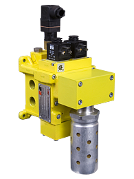
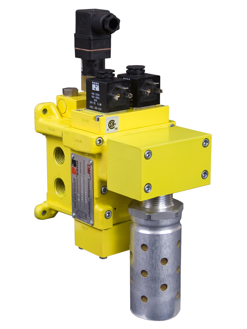
DM1 Series C Double Valve Product Overview
The DM1 Series C Safe Exhaust valves are dual valves used to block the supply and remove the downstream pressure from the circuit or machine. It is integrated into the electrical safety system to remove potentially hazardous energy in order to provide employees safe access to a machine or zone.
By quickly removing the pneumatic energy with a safety valve, determined by the risk assessment, the safety system integrity is maintained allowing the employee to complete their tasks safely and rapidly.
Please refer to the side and below for links to easily navigate and download ROSS Controls DM1 Series C Double Valve Catalogs, Installation Instructions, and technical data. Additionally, you have the option to filter through all available options to discover the DM1 Series C Double Valve variant that meets your requirements.
loading...
loading...
Product Overview
The ROSS Controls DM1 Series C is a redundant dual-poppet safe exhaust double valve that achieves Safety Category 4, Performance Level e (PL e) per ISO 13849-1:2015 and SIL 3 per IEC 62061 when integrated with proper safety controls. This represents the highest achievable safety category for pneumatic control valve technology and is the appropriate selection for applications where the risk assessment identifies high severity, frequent exposure, and limited possibility of avoiding the hazard.
The DM1 Series C uses two identical valve elements operating in tandem. Both solenoids must be simultaneously de-energized to exhaust downstream pressure, and both poppets must shift to the safe (exhausted) condition for the safety function to be complete. Internal dynamic monitoring continuously tracks the synchronized movement of both valve elements. If one element fails to shift or shifts asynchronously relative to the other, the monitoring circuitry latches the system in the safe (exhausted) condition and signals a fault.
The DM1 Series C uses automatic reset: when the abnormality clears itself upon removal of electrical power from both solenoids, the valve is ready to operate again without manual intervention. This distinguishes the DM1 from the DM2C Series, which uses a manual solenoid reset that retains fault memory even after power removal, requiring a deliberate operator reset action before the machine can restart. The DM1's automatic reset is appropriate for applications where the control system architecture manages the safety state transition and where process continuity is more important than latching fault retention.
Feedback to the machine control system is provided by a solid-state pressure sensor with both normally open (NO) and normally closed (NC) outputs. This sensor reports whether the valve is in the ready-to-run condition or has experienced an abnormal function. The machine control system must be integrated to prevent a run signal until the fault is cleared and confirmed by the feedback sensor. The DM1 feedback sensor does not perform a lockout function; it is a status reporting device.
The DM1 Series C includes a high-flow, clog-resistant silencer. Inlet and outlet ports are provided on both sides of the body for flexible piping, with plugs for unused ports included. The valve is base-mounted with captive mounting screws for ease of valve replacement without disturbing field piping. SISTEMA Library files are available for download.
Key Engineering Features
- Safety Category 4, PL e (ISO 13849-1:2015) - Achieves the highest pneumatic valve safety category when integrated with proper safety controls, appropriate for high-severity, high-frequency risk applications requiring maximum risk reduction.
- SIL 3 (IEC 62061) - Safety Integrity Level 3 certification confirms suitability for integration into the most demanding functional safety architectures.
- Redundant Dual-Poppet Design - Two identical valve elements operating in tandem. Failure of either element to shift is detected by internal dynamic monitoring, maintaining the safe state and signaling a fault.
- Internal Dynamic Monitoring - Integrated dynamic monitoring continuously verifies synchronous movement of both valve elements. Asynchronous movement or failure to shift latches the valve in the safe (exhausted) condition automatically, without reliance on external monitoring hardware.
- Automatic Reset - When an abnormality clears upon removal of power to both solenoids, the valve is ready to run again without manual intervention. Appropriate for systems where control architecture manages safety state transitions.
- Solid-State Pressure Sensor Feedback - Factory-installed solid-state pressure sensor with both NO and NC contacts provides ready-to-run or fault status feedback to the machine control system. Machine controls must prevent run signal until fault is cleared.
- Dirt-Tolerant, Wear-Compensating Poppet Design - Poppet geometry provides inherent dirt tolerance and automatic wear compensation for quick response and high flow capacity sustained over millions of cycles.
- PTFE Backup Piston Rings - Extends valve endurance and enables reliable operation with or without in-line lubrication.
- High-Flow Clog-Resistant Silencer Included - Factory-installed high-flow silencer on the exhaust port provides immediate noise reduction. Clog-resistant design reduces maintenance requirements.
- Flexible Inlet and Outlet Porting - Inlet and outlet ports on both sides of the body with plugs for unused ports. Captive valve-to-base mounting screws simplify replacement without disturbing field piping.
- Base Mount Design - Base-mounted configuration with captive screws allows valve replacement without disconnecting field piping, reducing maintenance downtime.
- SISTEMA Library Support - Downloadable SISTEMA Library files for ISO 13849-1 safety function documentation and PL e verification.
Technical Specifications
General Specifications
| Parameter | Specification |
| Safety Category | Category 4 |
| Performance Level | PL e per ISO 13849-1:2015 |
| Safety Integrity Level | SIL 3 per IEC 62061 |
| Monitoring Type | Internal dynamic monitoring |
| Reset Type | Automatic (clears on removal of power to both solenoids) |
| Valve Function | Redundant 3/2 single solenoid |
| Construction | Dual poppet |
| Actuation | Electrical (solenoid), 24 VDC |
| Feedback Sensor | Solid-state pressure sensor, NO and NC contacts |
| Feedback Sensor Supply Voltage | 8-30 VDC |
| Feedback Sensor Current Consumption | Less than 4 mA |
| Feedback Connection | M12 connector |
| Power Consumption | 5.8 watts nominal; 6.5 watts maximum |
| Solenoid Connection | EN 175301-803 Form A |
| Voltage | 24 VDC |
| Operating Pressure Max | 150 psig (10.3 bar) |
| Pilot Supply | Internal |
| Example Inlet / Outlet / Exhaust Sizes (Size 2) | 3/8" / 3/8" / 3/4" |
| Flow (Size 2, Ports 1-2) | 2.2 Cv (2,200 Nl/min) |
| Flow (Size 2, Ports 2-3 exhaust) | 3.6 Cv (3,500 Nl/min) |
| Mounting | Base mount |
| Thread Type | NPT and G (BSPP) |
| Ambient Temperature | 15 to 122 F (-10 to 50 C) |
| Media Temperature | 40 to 175 F (4 to 80 C) |
| Flow Media | Filtered, lubricated or unlubricated (mineral oils per DIN 51519, viscosity classes 32-46) |
| Valve Body Material | Cast aluminum |
| Poppet/Spool Material | Acetal and stainless steel |
| Seal Material | Buna-N |
| Piston Rings | PTFE backup |
| Silencer | High-flow, clog-resistant silencer included |
| Certifications | DGUV, CE, EAC, CSA/UL |
Certifications & Compliance
| Certification/Standard | Detail |
| Safety Category / PL | Category 4, PL e per ISO 13849-1:2015 when integrated with proper safety controls. |
| Safety Integrity Level | SIL 3 per IEC 62061. |
| DGUV Certification | DGUV (Deutsche Gesetzliche Unfallversicherung) certified for use in European industrial safety systems, including press and forming machine applications. |
| CE Marking | CE marked per EU Machinery Directive 2006/42/EC. |
| EAC Declaration | EAC (Eurasian Conformity) declaration for Russia and Eurasian Economic Union markets. |
| CSA/UL Certification | CSA/UL listed for North American market compliance. |
| SISTEMA Library | Downloadable SISTEMA Library files for ISO 13849-1 PL e verification. |
Typical Applications & Industries
Metal Forming and Stamping
- Mechanical and hydraulic power presses where OSHA 29 CFR 1910.217 and ANSI B11.1 require the highest level of pneumatic safety control, and the Category 4, PL e DM1 provides the required control reliability for high-stroke-rate press operations.
- Stamping and deep-drawing presses on automotive body components where continuous, high-frequency cycling demands the sustained Category 4 performance of a redundant dual-poppet design.
- Metal blanking and progressive die operations where simultaneous loss of both valve elements is detected immediately by internal monitoring, preventing a single-point failure from allowing an unguarded stroke.
Automotive Body and Powertrain Manufacturing
- Transfer press lines and tandem press systems where the Category 4 DM1 meets the highest risk-reduction requirements for automated press operations with frequent worker access for die setting and maintenance.
- Engine assembly and test cell pneumatic controls where SIL 3 compliance is mandated by facility safety engineering standards.
- Robotic welding and assembly cells requiring Category 4 pneumatic safety valves for clutch-brake control circuits that govern robot movement near workers.
Rubber and Plastics Processing
- Rubber vulcanizing presses and compression molding machines where trapped high-pressure steam and pneumatic circuits create severe injury hazard if pressure is not positively confirmed absent before mold access.
- Injection molding machine hydraulic-pneumatic systems requiring Category 4 energy isolation for mold change operations with frequent, regular maintenance access.
Material Handling and Industrial Machinery
- Pneumatically actuated industrial robots and collaborative robot safety interfaces where Category 4 pneumatic safe exhaust is specified as part of a documented safety function.
- Heavy-duty clamping and holding fixtures on machining centers where workpiece release during machining would represent a Category 4 risk requiring maximum-reliability pneumatic control.
- Conveyor system sorting and transfer gates with large pneumatic actuators requiring Category 4 energy removal before operator access for jam clearance.
Woodworking and Panel Processing
- Multi-opening hot press systems for plywood and MDF production where large-area pneumatic platens and steam-heated dies represent high-severity hazards requiring Category 4 safe exhaust.
- CNC machining center vacuum table systems requiring the highest category safe exhaust for workpiece hold-down release confirmation during automated loading cycles.
General High-Risk Industrial Applications
- Any application where the risk assessment per ISO 12100 and ISO 13849 determines a required PL of PL e and the pneumatic circuit's contribution to the safety function must meet Category 4 control architecture.
- OEM machine builders designing to EU Machinery Directive compliance who must demonstrate Category 4, PL e pneumatic safe exhaust in the machine technical file for CE marking.
- Facilities operating under ISO 45001 or OSHA VPP where maximum practicable risk reduction is the standard and Category 4 valve selection is required by corporate safety engineering policy.
Ordering and Model Number Configuration
The DM1 Series C model number encodes valve function, body size, port configuration, monitoring type, reset type, voltage, and thread type. The example model DM1CNB21A32 identifies: DM1C Series, NPT thread, Basic Size 2, 3/8" inlet/outlet, 3/4" exhaust, 24 VDC, automatic reset. Contact ROSS Controls for the full configurator.
|
DM1 Series C Model Number Structure:
DM1C Series designation (DM1C = Category 4 Double Valve, Internal Monitoring, Automatic Reset)
N/D Thread type (N = NPT; D = G/BSPP)
B Revision level
21 Basic size and port size code
A Voltage/electrical option code
32 Additional configuration codes |
Standard voltage: 24 VDC.
Solenoid connection: EN 175301-803 Form A standard. 5-pin M12 solenoid connector available on some configurations.
Feedback sensor connects via M12 connector.
NPT and G (BSPP) thread options available.
Multiple body sizes available for different flow requirements. Contact ROSS for complete size matrix.
Certifications: DGUV, CE, EAC, CSA/UL. Specify required certification when ordering.
SISTEMA Library files downloadable at rosscontrols.com.
Contact ROSS Controls at (800) 438-7677 for full variant listing, dimensional drawings, and application engineering support.
Accessories
Additional Pressure Gauges and Transducers
Analog and digital pressure measurement devices for downstream pressure monitoring and system commissioning. Digital transducers with 4-20 mA output available for PLC integration.
Lockout L-O-X Valves
Manual lockout valves for upstream energy isolation, used with the DM1 Series C for complete pneumatic lockout/tagout capability during maintenance activities.
ROSS MD Series FRL Units
Filter-Regulator-Lubricator units for upstream air preparation. 5-micron filtration protects the DM1 dual-poppet design from contamination-related degradation.
Mounting Hardware
Panel mounting brackets, port blocks, and end ports for flexible system integration and serviceability.
Related Products & Accessories
- DM2C Series Double Valve (Category 4, PL e, Manual Reset) - Same redundant dual-poppet architecture as DM1 but with manual solenoid reset for latching fault memory. https://www.rosscontrols.com/en/series/1295-dm2c-series-double-valve
- M35 Series Double Valve (Category 4, PL e, External Monitoring) - Redundant dual-poppet double valve with external solid-state pressure sensor monitoring. https://www.rosscontrols.com/en/series/1296-m35-series-double-valve
- RSe Series Double Valve (Category 4, PL e, External Monitoring) - Redundant spool-type double valve with PNP proximity sensors for external monitoring. https://www.rosscontrols.com/en/series/1297-rse-series-double-valve
- DM2 Series C Explosion Proof (Category 4, PL e) - Explosion-proof variant of the DM2C for hazardous location (ATEX/NEC) applications. https://www.rosscontrols.com/en/series/1308-dm2-series-c-safe-exhaust-valve-explosion-proof
- SV27 Series Single Valve (Category 2, PL c) - Single valve with DPST safety switch for 99% DC Category 2 applications. https://www.rosscontrols.com/en/series/1293-sv27-series-single-valve
- Safe Air Entry Assembly with DMC Series - Complete air entry assembly with Lockout L-O-X, FRL, and DM1 or DM2 safe exhaust valve. https://www.rosscontrols.com/en/series/1286-safe-air-entry-assembly-with-dmc-series-safe-exhaust-valve
Frequently Asked Questions (FAQ)
Q: What safety performance does the DM1 Series C achieve?
A: The DM1 Series C achieves Safety Category 4, Performance Level e (PL e) per ISO 13849-1:2015 and SIL 3 per IEC 62061 when properly integrated with appropriate safety controls. Category 4 is the highest achievable category for pneumatic control valves and is required for applications where the risk assessment identifies high severity, frequent worker exposure, and limited possibility of avoiding the hazard.
Q: What is internal dynamic monitoring and how does it work?
A: Internal dynamic monitoring is an integrated electronic function that continuously tracks the synchronized movement of both valve elements during every actuation and de-actuation cycle. If one element fails to shift (sticking closed) or shifts asynchronously relative to the other, the monitoring circuit immediately detects the discrepancy and latches the valve in the safe (exhausted) condition. This detection happens without reliance on any external monitoring hardware, which is the key distinction of internal monitoring versus external monitoring architectures.
Q: What is the difference between the DM1 Series C and the DM2C Series?
A: Both valves achieve Category 4, PL e, SIL 3 and use the same redundant dual-poppet architecture with internal dynamic monitoring. The key difference is the reset type. The DM1 uses automatic reset: when the fault clears on removal of power to both solenoids, the valve is ready to run again without operator intervention. The DM2C uses manual reset via an integrated solenoid: the fault condition latches even after power removal, and a deliberate solenoid reset signal is required to restore the valve to ready-to-run status. The DM2C's latching reset provides positive confirmation that an operator has acknowledged the fault before machine restart.
Q: What does the feedback sensor report and what must the machine control do?
A: The solid-state pressure sensor reports whether the valve is in the ready-to-run condition (normal) or has experienced an abnormal function (fault). The machine control system must prevent a run signal from being issued until the fault is cleared and the feedback sensor confirms the ready-to-run state. The feedback sensor does not perform a physical lockout function and should not be relied upon as the sole means of preventing machine restart after a fault.
Q: What is the residual outlet pressure after a fault condition is detected?
A: On detection of an asynchronous valve element failure, the internal monitoring system latches the valve in the safe condition. The design target is residual outlet pressure of less than 1 percent of supply pressure in the fault/latched condition. The actual value depends on the specific size and configuration.
Q: What are the available body sizes and flow capacities?
A: The DM1 Series C is available in multiple basic sizes. The documented Size 2 variant (model DM1CNB21A32) has 3/8 inch inlet and outlet ports with 3/4 inch exhaust and flows of 2.2 Cv (2,200 Nl/min) supply and 3.6 Cv (3,500 Nl/min) exhaust. Larger sizes are available for higher flow requirements. Contact ROSS Controls for the complete size matrix.
Q: What is the maximum operating pressure?
A: The maximum operating pressure is 150 psig (10.3 bar).
Q: What certifications does the DM1 carry?
A: The DM1 Series C carries DGUV certification (German statutory accident insurance), CE marking (EU Machinery Directive), EAC declaration (Eurasian Economic Union), and CSA/UL listing (North America). SISTEMA Library files are available for ISO 13849-1 documentation.
Q: Can the DM1 be used in conjunction with a Lockout L-O-X valve?
A: Yes. For full lockout/tagout compliance per OSHA 29 CFR 1910.147, the DM1 should be combined with an upstream Lockout L-O-X valve that provides manual physical energy isolation. The DM1 provides automatic safe exhaust on de-energization; the L-O-X valve provides the padlockable mechanical energy isolation required for maintenance lockout procedures. ROSS offers complete Safe Air Entry Assembly configurations that combine these components.
Q: Does the DM1 require lubrication?
A: No. PTFE backup piston rings and poppet design allow reliable operation without in-line lubrication. If lubrication is used, it must be a mineral oil per DIN 51519, viscosity classes 32 to 46. Avoid synthetic or phosphate-ester-based lubricants incompatible with Buna-N seals.
Q: What is the SISTEMA Library used for?
A: The SISTEMA Library file contains the safety parameters (B10D, PFHD, DC, MTTFD, Category, PL) for the DM1 Series C in a format compatible with the IFA SISTEMA software. Engineers use this software to calculate and document the Performance Level of safety functions per ISO 13849-1 for inclusion in the machine technical file.
Q: How is the DM1 installed?
A: The DM1 is base-mounted. Captive valve-to-base mounting screws retain the valve body to the base without requiring tool access to the mounting fasteners during valve replacement. Inlet and outlet ports on both sides of the body allow flexible piping approach. After piping, electrical connections to solenoid and feedback sensor must be made to the machine safety control system as described in the installation instructions.
Installation & Maintenance Guidelines
- Mount the DM1 base assembly first, then connect all field piping to the base. Captive screws secure the valve body to the base, allowing valve replacement without disturbing piping.
- Connect supply to one inlet port. Plug the unused inlet port with the included plug. Connect the machine circuit to one outlet port. Plug the unused outlet port.
- Do not restrict the exhaust port or the included silencer. Ensure silencer flow capacity is not exceeded. Replace silencer if clogged.
- Wire both solenoid connectors (EN 175301-803 Form A) to the machine safety controller outputs. Both solenoids must be simultaneously de-energized to achieve the safe exhaust condition.
- Wire the M12 feedback sensor connector to the safety controller's sensor input. Configure the controller to monitor NO and NC contacts for ready-to-run and fault states.
- Program the machine control system to prevent machine restart if the feedback sensor indicates a fault condition. Do not allow restart until fault is cleared and sensor confirms ready-to-run.
- Supply filtered compressed air. 5-micron filtration upstream recommended. Operating pressure: up to 150 psig (10.3 bar).
- Perform commissioning test: energize both solenoids simultaneously to supply the machine circuit; de-energize both solenoids simultaneously to exhaust; verify feedback sensor reports ready-to-run after exhaust.
- Simulate a fault condition (delay one solenoid by a controlled means per installation instructions) and verify the valve latches in the safe state and the feedback sensor reports fault.
- Document all commissioning results and SISTEMA calculations in the machine technical file.
Warranty & Global Support
ROSS Controls provides a one-year warranty on all products, covering defects in material and workmanship from date of purchase.
Technical support: 1-888-TEK-ROSS (1-888-835-7677). Customer service: 1-800-GET-ROSS (1-800-438-7677).
Global support through ROSS offices in the USA (Ferndale, Michigan), Canada, Germany, France, United Kingdom, Brazil, India, China, and Japan.
SISTEMA Library files, dimensional drawings, CAD models, and certifications available at rosscontrols.com.
Download Catalog: https://www.rosscontrols.com/en/series/1294-dm1-series-c-double-valve
Download Documents
DM1 Series C Double Valve