SV27 Series Pilot Operated Redundant Check Valves Safety Category. 3 PL e, External Monitoring
- Dirt tolerant, wear compensating for quick response and high flow capacity
- Poppet construction for near zero leakage & dirt tolerance
- Senses internal position & state
- Electrical feedback via DPST switch (Double-Pole Single-Throw)
- Directly operated safety-rated force-guided positive-break status switch (DPST)
- A diagnostic coverage (DC) of up to 90% can be obtained by monitoring the safety switch status
- SISTEMA Library available for download
SV27 Series Pilot Operated Redundant Check Valves Product Overview
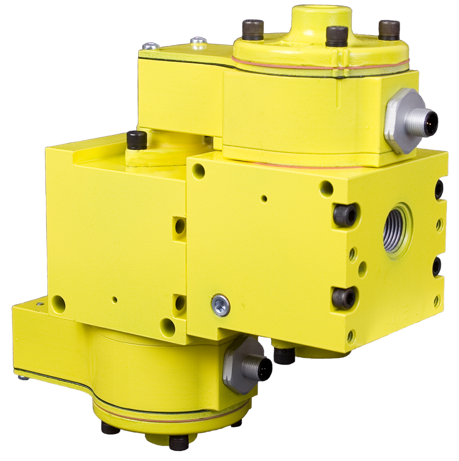
Pilot Operated Check valves are designed to trap pressure in order to hold a cylinder in place when a safety event occurs. The SV27 Series Sensing Valve uses a safety-rated DPST switch to monitor the valve's operating position. The SV27 PO Check valves can be used for load holding functions in Category 2 (single) or Category 3 (redundant) applications with proper integration and monitoring. The feedback switch informs the controls that the valve internals have shifted properly.
Please refer to the side and below for links to easily navigate and download ROSS Controls SV27 Series Pilot Operated Redundant Check Valves catalogs, installation instructions, and technical data. Additionally, you have the option to filter through all available options to SV27 Series Pilot Operated Redundant Check Valves variant that meets your requirements.
loading...
loading...
Product Overview
The ROSS Controls SV27 Series Pilot Operated Redundant Check Valves are a dual-valve assembly designed for load holding and safe cylinder position holding applications requiring Safety Category 3, Performance Level e (PL e) per ISO 13849-1. The redundant configuration uses two SV27 pilot operated check valves in series, each with an integrated safety-rated DPST (Double-Pole Single-Throw) switch, providing two independent channels of load holding with two independent position feedback signals for external monitoring.
This series is the highest-rated pilot operated check valve product in the ROSS Controls load-holding portfolio. When used with a properly designed customer-supplied safety control system that monitors both DPST switch outputs, the redundant SV27 assembly achieves Category 3 PL e and SIL 2 (with SIL 3 achievable in configurations with HFT greater than or equal to 1 per IEC 61508). A diagnostic coverage of up to 90 percent can be obtained by monitoring the safety switch status of both valves.
Each valve in the assembly uses the proven ROSS poppet technology: dirt-tolerant, wear-compensating, face-sealing poppet construction providing near-zero internal leakage, high flow capacity, and quick response. The redundant arrangement means that even if one valve element fails in the open state, the second valve continues to hold the cylinder position and the safety function is maintained. The DPST switch on the failed valve provides fault detection feedback to the controller.
The SV27 redundant series is available in 24 VDC and 110/120 VAC solenoid configurations and in pressure-controlled (normally closed) variants. Port sizes are 1/2" and 3/4" with NPT or G (BSPP) thread options. Electrical connection uses CNOMO connectors for both solenoids and both DPST switches. The assembly carries DGUV certification, CE marking, CSA/UL certification, and EAC declaration of conformity. SISTEMA library files are available for download.
Key Engineering Features
- Redundant Dual Poppet Load Holding for Category 3 PL e - Two SV27 pilot operated check valves in series provide redundant load holding. If one valve element fails in the open (non-holding) state, the second valve maintains cylinder position and prevents uncontrolled motion. This single-fault tolerance (HFT = 1) architecture is the basis for Category 3 PL e performance.
- Dual DPST Switches for External Monitoring - Each valve in the assembly includes an independent, directly operated safety-rated DPST switch. Both switches provide independent position feedback to the safety controller, enabling fault detection across both load-holding channels and supporting up to 90 percent diagnostic coverage per channel.
- Category 3 PL e Achievement - When used with a customer-supplied safety controller that monitors both DPST switch outputs from both valves, the assembly achieves Safety Category 3, Performance Level e (PL e) per ISO 13849-1, and SIL 2 per IEC 61508/61511. SIL 3 is achievable in higher-HFT configurations.
- Force-Guided Positive-Break DPST Switches - Both integrated DPST switches use force-guided, positive-break mechanism designs that directly actuate from the valve position. Contact welding cannot prevent fault detection, ensuring accurate position reporting from both channels even after extended service.
- 90 Percent Diagnostic Coverage - Monitoring both NO and NC contacts of each DPST switch with all changes in valve state achieves up to 90 percent diagnostic coverage per channel, satisfying the high DC requirement for Category 3 PL e compliance.
- ROSS Poppet Technology on Both Channels - Both valve elements use ROSS poppet construction: dirt-tolerant, wear-compensating, face-sealing design with near-zero leakage, consistent response times, and self-cleaning high-velocity flow paths. Performance is maintained across millions of cycles per valve.
- Solenoid or Pressure Control with Simultaneous Actuation - Both valves in the assembly are actuated simultaneously by the same solenoid pilot signal or pneumatic pilot pressure. De-energizing the pilot simultaneously removes the pilot signal from both valves, closing both poppets and establishing the redundant load-hold state in a single control action.
- DGUV, CE, CSA/UL, and EAC Certifications - Full global certification: DGUV (Sicherheit gepruft), CE (EU Machinery Directive 2006/42/EC), CSA/UL (North American), and EAC (Eurasian Economic Union). Suitable for North American, European, and international safety-critical installations without additional valve-level certification.
- CNOMO Electrical Connection - CNOMO connectors are used for both solenoids and both DPST switches on the redundant assembly. Pre-wired cable assemblies are available to simplify multi-channel panel wiring.
- SISTEMA Library Available - Downloadable SISTEMA library files provide pre-validated safety data blocks for the SV27 redundant assembly, enabling direct import into SISTEMA for ISO 13849-1 PL e verification without manual data entry.
Technical Specifications
General Specifications
| Parameter | Specification |
| Series | SV27 (Redundant Assembly) |
| Valve Function | 2/2 Redundant Pneumatic Pilot Operated Check (PO Check) |
| Default State | Normally Closed (both checks active) |
| Construction | Dual Poppet (redundant) |
| Number of Valves | Two SV27 check valves in series |
| Actuation | Electrical (Solenoid Pilot) or Pneumatic (Pressure Controlled) |
| Mounting | Inline |
| Body Size | 3/4" |
| Port Sizes Available | 1/2", 3/4" |
| Thread Types | NPT and G (BSPP) |
| Operating Pressure | 40 to 150 psig (2 to 10 bar) |
| Voltage (Solenoid Models) | 24 VDC or 110/120 VAC |
| Power Consumption (24 VDC) | 6 watts per solenoid (2 solenoids total) |
| Power Consumption (110/120 VAC) | 87 VA inrush, 30 VA holding per solenoid |
| Electrical Connection | CNOMO (standard industrial mini connector) |
| DPST Switches | Two (one per valve); force-guided, positive-break design |
| DPST Switch Rating | 2.5 A / 120 VAC maximum; 50 mA / 24 VDC minimum |
| Flow Media | Filtered Air (5-micron minimum recommended) |
| Valve Body Material | Cast Aluminum |
| Poppet Material | Acetal and Stainless Steel |
| Seal Material | Buna-N; Fluorocarbon |
| Diagnostic Coverage | Up to 90% DC per channel (via monitoring of both DPST switch contacts per valve) |
| B10D Value | 20,000,000 cycles per valve element |
| MTTFD | 98.15 years per channel (at 7,360 cycles/year) |
| PFHD | 2.35 x 10^-8 per hour per channel |
Temperature Ratings
Temperature ratings apply to all SV27 redundant assembly configurations. Media must be filtered to 5-micron or finer to maintain poppet seat integrity in both valve elements.
| Configuration | Ambient Temperature | Media Temperature |
| All SV27 Redundant Assembly Variants (Buna-N and Fluorocarbon seals) | 40 to 120 F (4 to 50 C) | 40 to 175 F (4 to 80 C) |
Electrical Data (Solenoid Pilot Valves)
Both solenoids in the redundant assembly must be de-energized simultaneously to achieve load holding. Both DPST switch outputs must be monitored independently by the safety controller.
| Voltage | Power Consumption |
| 24 VDC | 6 watts per solenoid (12 watts total for two solenoids) |
| 110/120 VAC, 50/60 Hz | 87 VA inrush, 30 VA holding per solenoid |
Flow Performance Data
Flow performance for SV27 redundant assembly representative variants. Flow values are for the 1-2 (free-flow) direction through the complete series assembly. Pilot-opened reverse flow is rated equivalently when both pilot signals are applied simultaneously.
| Model | Port 1 Size | Port 2 Size | Ports 1-2 Flow | Length | Width | Height | Weight | Voltage |
| SV27NC555408CSAA1D | 1/2" NPT | 1/2" NPT | 3.8 Cv (3,739 Nl/min) | 8.3 in (211 mm) | 3.3 in (84 mm) | 13.2 in (335 mm) | 10 lb (4.5 kg) | 24 VDC |
| SV27NC555408CSAA1A | 1/2" NPT | 1/2" NPT | 3.8 Cv (3,739 Nl/min) | 8.3 in (211 mm) | 3.3 in (84 mm) | 13.2 in (335 mm) | 10 lb (4.5 kg) | 110/120 VAC |
Certifications & Compliance
| Certification/Standard | Detail |
| Safety Category / PL Rating | Category 3, Performance Level e (PL e) per ISO 13849-1 when used with a customer-supplied safety control system that monitors both DPST switch outputs from both valves with proper external monitoring. |
| Safety Integrity Level | SIL 2 per IEC 61508 and IEC 61511 per channel; SIL 3 achievable in configurations with HFT greater than or equal to 1, enabling integration into high-demand safety instrumented systems. |
| B10D Value | 20,000,000 cycles per valve element, providing the statistical basis for safety lifetime calculations in SISTEMA and other functional safety tools. |
| MTTFD | 98.15 years per channel at 7,360 cycles per year. |
| PFHD | 2.35 x 10^-8 per hour per channel, the probability of dangerous failure per hour for SIL and PL calculations. |
| Diagnostic Coverage | Up to 90% DC per channel achieved by monitoring both NO and NC contacts of each DPST switch with all changes in valve control state. |
| DGUV Certification | Yes - DGUV certified (Sicherheit gepruft / tested safety), confirming compliance with German Social Accident Insurance safety requirements for pneumatic components. |
| CE Marking | Yes - CE marking for conformity with the EU Machinery Directive 2006/42/EC, authorizing sale and installation throughout the European Economic Area. |
| CSA/UL Certification | Yes - CSA/UL certified for the North American market. |
| EAC Declaration | Yes - EAC conformity declaration for Eurasian Economic Union markets. |
| Enclosure Protection | IP65 per DIN 40050, providing dust-tight protection and resistance to low-pressure water jets. |
Typical Applications & Industries
High-Risk Vertical Load Holding
- Heavy vertically loaded cylinders in mechanical presses, hydraulic/pneumatic hybrid presses, and large-bore forming presses where a single valve failure must not result in uncontrolled descent of the tooling or ram. The redundant SV27 ensures Category 3 load holding with fault detection.
- Industrial robots with pneumatic counterbalance cylinders where the payload and arm weight require redundant pressure holding to prevent gravity collapse in the event of a valve failure during a safety stop.
- Aerial work platforms and elevated work stations with pneumatic lift cylinders where a single-channel load-holding failure creates a fall hazard. Category 3 PL e is required by ISO 13849-1 for Type C machine standards governing elevated personnel platforms.
- Die casting machines with pneumatic ejector and clamp cylinders that operate under high force and require fault-tolerant load holding to prevent unintended die opening or ejector advance during mold dwell.
Automotive and Heavy Manufacturing
- Automotive body-in-white welding fixtures where category 3 load holding ensures weld quality and prevents workpiece movement during the weld cycle even in the event of a valve malfunction.
- Large stamping press binder and cushion cylinder circuits where the redundant SV27 provides fault-tolerant load holding on each cylinder axis and the DPST switch outputs enable press-integrated safety monitoring.
- Engine and transmission assembly machines where pneumatic cylinder load holding must be maintained reliably during precision fastening or measurement operations with access hatches open.
- Steel processing line tension cylinder circuits in strip mills and coil processing lines where cylinder position holding under high strip tension requires redundant, monitored load holding to prevent strip breaks and equipment damage.
Packaging, Food, and Pharmaceutical Manufacturing
- High-throughput packaging lines where Category 3 safety functions are required by machine builders' risk assessments for cylinder axes that operate in proximity to operators during format change or jam clearance.
- Food and beverage filling and capping machines where pneumatic cylinder load holding under product load must be fault-tolerant, and CE certification of the valve component is required for EU market compliance.
- Pharmaceutical manufacturing equipment in clean environments where DGUV and CE certification of the SV27 assembly satisfies regulatory compliance requirements without additional third-party testing.
- Confectionery and baking equipment with pneumatic mold cylinders that must hold position during the forming dwell while allowing operator access for product inspection through guarded access openings.
CE Marking and Regulatory Compliance Applications
- Any machine requiring Category 3 PL e or higher for a cylinder load-holding safety function per the machine's ISO 13849-1 risk assessment, where the pre-validated SISTEMA data from ROSS reduces the documentation burden.
- Export machines destined for the European Economic Area where the Machinery Directive 2006/42/EC requires both the Category 3 safety function and CE marking on the safety component.
- North American installations requiring CSA/UL listed components in the pneumatic safety circuit, where the SV27 redundant assembly provides both the safety rating and the listing without separate sourcing of listed components.
- DGUV-regulated German facilities where the German Social Accident Insurance requires third-party certified pneumatic safety components for load-holding functions on machinery classified under DGUV regulations.
Ordering and Model Number Configuration
The SV27 Series redundant check valve model number encodes actuation type, port configuration, body size, voltage, electrical connection, and redundant monitoring designation. Contact ROSS Controls at (800) 438-7677 or visit rosscontrols.com for the full configurator and current pricing.
|
SV27 Series Redundant Check Valve Model Number Structure:
SV27 NC 5 5 5 4 0 8 C S A A 1 D | | | | | | | | | | | Revision Level: D = Redundant Assembly | | | | | Monitoring Code: 1 = Redundant dual valve | | | | | Electrical Connection: A = CNOMO | | | | Switch Type: A = DPST (one per valve) | | | | Safety Function: S = Redundant | | | Connection: C = CNOMO | | | Valve Function: 8 = 2/2 PO Check (redundant) | | Thread/Seal Code | | Body/Port Size Code for Valve 2 | Body/Port Size Code for Valve 1 | Port Configuration Pilot Type Code: 5 = Series Assembly Control Type: NC = Normally Closed / Pressure Controlled; DC = Solenoid Pilot Series: SV27 Redundant |
Actuation type: NC = pressure-controlled (normally closed) redundant assembly; DC = solenoid pilot controlled redundant assembly.
Voltage codes for solenoid models: 08 = 24 VDC; 07 = 110/120 VAC 50/60 Hz.
Revision Level D indicates the redundant dual-valve assembly. Single-valve (Category 2) SV27 variants use the 1306 series.
Thread types: standard models use NPT threads. G (BSPP) thread variants are designated with 'D' prefix.
SISTEMA library files and safety data sheets are available for download at rosscontrols.com.
Contact ROSS Controls at (800) 438-7677 for special configurations, larger port sizes, or applications outside standard operating parameters.
SV27 Redundant Check Valve Example Model Numbers
| Model Number | Port Size | Thread | Voltage | Safety Category |
| SV27NC555408CSAA1D | 1/2" NPT | NPT | 24 VDC | Category 3 PL e |
| SV27NC555408CSAA1A | 1/2" NPT | NPT | 110/120 VAC | Category 3 PL e |
Accessories
CNOMO Electrical Cable Assemblies
Pre-wired CNOMO cable assemblies for solenoid and DPST switch connections are available in standard lengths, simplifying the multi-channel wiring of both solenoids and both switch channels on the redundant assembly.
Pressure Verification Accessories
Optional pressure verification port accessories include a visual pop-up pin pressure indicator (Model 988A30) and an electrical pressure switch preset at 5 psi falling edge (Model 586A86). These verify cylinder pressure release on both channels before permitting operator access, supporting Category 3 energy verification requirements.
| Accessory | Model | Function |
| Visual Pressure Indicator | 988A30 | Pop-up pin confirms pilot pressure; visual confirmation only |
| Electrical Pressure Switch | 586A86 | Preset 5 psi falling edge; DIN EN 175301-803 Form A connector; dual-channel electrical feedback to safety controller |
Exhaust Silencers
ROSS aluminum exhaust silencers are available for all SV27 port sizes. Both the primary valve and secondary valve exhaust ports must be fitted with appropriately sized silencers. Verify each silencer flow capacity equals or exceeds the corresponding circuit exhaust flow requirements.
L-O-X Lockout Control
The L-O-X manual lockout accessory integrates with the SV27 assembly to provide positive energy isolation for LOTO procedures on both valve channels simultaneously. The L-O-X mechanism prevents valve re-energization while the lockout device is engaged.
Related Products & Accessories
- SV27 Series Single PO Check Valves for External Monitoring (1306) - Single-valve SV27 for Category 2 PL c load holding with integrated DPST switch - the step below the redundant assembly in safety integrity. https://www.rosscontrols.com/en/series/1306-sv27-series-pilot-operated-check-valves-for-external-monitoring
- 27 Series Pilot Operated Check Valves (1305) - Category 1 PL c inline pilot operated check valves for applications where external monitoring is not required. https://www.rosscontrols.com/en/series/1305-27-series-pilot-operated-check-valves
- CC4 Series Double Valve (1303) - 4/3 closed-center double safety valve for bidirectional safe cylinder control and Category 4 PL e load holding - a complementary high-performance safety directional valve. https://www.rosscontrols.com/en/series/1303-cc4-series-double-valve
- 19 Series Pilot Operated Check Valves (1304) - Compact right-angle Category 1 PL c pilot operated check valves for small-bore panel-mounted circuits. https://www.rosscontrols.com/en/series/1304-19-series-pilot-operated-check-valves
- L-O-X Lockout Valves (Energy Isolation) - Lockout valves for safe energy isolation during maintenance per OSHA lockout/tagout requirements. https://www.rosscontrols.com/en/series/1287-lockout-valves-15-series
- Safe Air Entry Assemblies with SV27 - Pre-engineered safe air entry assemblies incorporating the SV27 for integrated energy control at the machine air supply inlet. https://www.rosscontrols.com/en/series/1284-safe-air-entry-assembly-with-sv27
Frequently Asked Questions (FAQ)
Q: What is the redundant SV27 assembly and how does it differ from the single SV27?
A: The SV27 redundant assembly consists of two SV27 pilot operated check valves mounted in series, each with an independent DPST safety switch. The two valves form a dual-channel load-holding circuit: both must be in the open state simultaneously for air to flow to the cylinder, and both must be in the closed state for load holding to be established. If one valve fails in the open state, the second maintains load holding. This redundant architecture (HFT = 1) enables Category 3 PL e performance, one level above the single SV27 (1306) which achieves Category 2 PL c.
Q: What safety category and PL does the SV27 redundant assembly achieve?
A: The SV27 redundant assembly achieves Safety Category 3, Performance Level e (PL e) per ISO 13849-1 when used with a customer-supplied safety controller that monitors both DPST switch outputs. This is the same PL rating as the CC4 Series double valve, but the SV27 redundant assembly provides a unidirectional load-holding function (check function) rather than a bidirectional directional control function. SIL 2 per IEC 61508/61511 is achieved per channel; SIL 3 is achievable in HFT greater than or equal to 1 configurations.
Q: How does the redundant load holding work mechanically?
A: Both SV27 poppet check valves are installed in series in the pneumatic line between the directional control valve and the cylinder. Air flows freely from port 1 through both valves to the cylinder when both pilot signals are applied simultaneously. When the pilot signals are simultaneously removed, both poppets close independently. The cylinder is now trapped between two independent poppet seats. If one poppet seat leaks, the second poppet maintains the trapped pressure. The DPST switch on the valve that fails to hold reports the fault to the safety controller.
Q: What does Category 3 PL e mean for load holding?
A: Category 3 PL e per ISO 13849-1 means the safety function (load holding) is maintained when any single fault occurs within the safety system. For the SV27 redundant assembly, this means: a single poppet leak does not result in cylinder motion; a single DPST switch failure does not result in loss of fault detection capability; and the overall probability of dangerous failure per hour (PFHd) is consistent with PL e requirements for the intended application.
Q: Why are there two DPST switches on the redundant assembly?
A: Each SV27 valve in the redundant assembly has its own independent DPST switch that monitors that valve's position. The safety controller monitors both switch outputs independently. This provides two independent fault detection channels. If either valve fails to reach the correct position, its corresponding switch reports the discrepancy. Monitoring both switches also achieves the high diagnostic coverage required for Category 3 compliance and provides the safety controller with enough information to identify which channel has faulted.
Q: How must the safety controller use the two DPST switch outputs?
A: The safety controller must: (1) Monitor both NO and NC contacts of each DPST switch independently, using four contact inputs total. (2) Verify that both switch pair outputs confirm the expected valve state following every solenoid command change. (3) Register a fault if either switch does not confirm the correct state within the expected response time. (4) Inhibit machine restart until the faulted channel is identified and cleared. (5) The monitoring must be dynamic and continuous, not a one-time startup check. This monitoring architecture achieves the required 90 percent DC per channel.
Q: What is the difference between the SV27 redundant assembly and the CC4 Series double valve (1303)?
A: The SV27 redundant assembly provides a unidirectional, single-direction load-holding function: it traps pressure on one side of a cylinder to hold position. The CC4 Series provides a bidirectional function (4/3 directional valve with closed center): it controls cylinder extend and retract, and holds in the center position. Use the SV27 redundant assembly when only position holding (not directional control) is required for one cylinder port, and the CC4 when bidirectional control of a double-acting cylinder with load holding is required. Both achieve Category 3/4 safety levels.
Q: What certifications does the SV27 redundant assembly carry?
A: The SV27 redundant assembly carries: DGUV certification (Sicherheit gepruft, German Social Accident Insurance), CE marking (EU Machinery Directive 2006/42/EC), CSA/UL certification (North American market), and EAC declaration of conformity (Eurasian Economic Union). This is the same global certification package as the single SV27 (1306).
Q: What is the flow capacity of the SV27 redundant assembly?
A: The 1/2" NPT port redundant assembly (model SV27NC555408CSAA1D) achieves 3.8 Cv (3,739 Nl/min) through the complete series assembly. Flow capacity is lower than a single SV27 because the flow passes through two valves in series. For applications requiring higher flow with the same Category 3 PL e rating, contact ROSS Controls for larger body size options.
Q: What is the operating pressure range for the SV27 redundant assembly?
A: The SV27 redundant assembly operates at 40 to 150 psig (2 to 10 bar). The minimum 40 psig requirement applies to both valves in the assembly. Do not operate below 40 psig, as insufficient pressure may result in incomplete poppet actuation or inconsistent DPST switch actuation timing on one or both channels.
Q: How often should the SV27 redundant assembly be tested?
A: ROSS recommends functional testing of both DPST switches and both poppet sealing functions every 8 hours for load-holding applications. The safety controller should be programmed to execute an automated test cycle at this interval: command load-hold, verify both switch outputs confirm the hold state, then release and verify both switch outputs confirm the open state. This testing frequency is consistent with the proof test interval assumed in the published safety data.
Q: Is the SISTEMA library available for the SV27 redundant assembly?
A: Yes. ROSS Controls provides downloadable SISTEMA library files for the SV27 redundant assembly, enabling direct import into SISTEMA for ISO 13849-1 PL e verification. The library file includes the complete safety data for both valve channels and the redundant architecture, eliminating the need to manually configure the dual-channel block in SISTEMA. Download the library from rosscontrols.com/en/series/1307.
Installation & Maintenance Guidelines
- Mount the SV27 redundant assembly inline with port 1 (inlet to valve 1) connected to the directional control valve side and port 2 (outlet of valve 2) connected to the cylinder or actuator port. Reverse mounting eliminates both load-holding functions.
- Position the assembly as close to the cylinder port as possible to minimize the trapped air volume between the downstream poppet seat and the cylinder. Smaller trapped volumes reduce cylinder drift after the valves close.
- Connect both solenoid connectors to a common safety controller output that is de-energized when load holding is required. Both valves must receive the de-energize command simultaneously for proper redundant load holding to be established.
- Connect all four DPST switch contact inputs (NO and NC from valve 1 and NO and NC from valve 2) to independent safety controller input channels. Do not parallel the switch contacts or combine them into a single input; independent monitoring is required for Category 3 DC compliance.
- Configure the safety controller to monitor all four switch contact inputs after each solenoid command. The controller must: confirm valve 1 switch shows correct state; confirm valve 2 switch shows correct state; register a fault if either switch does not confirm correct state within the expected response window; and inhibit restart until the fault is cleared.
- Supply filtered compressed air at 5-micron or finer particle filtration upstream of the assembly. Both poppets require clean air to maintain seat integrity and consistent switch actuation timing.
- Verify supply pressure is within 40 to 150 psig (2 to 10 bar) before commissioning. Check that pilot pressure is available and within range for both valves.
- Ensure ambient temperature at the installation location is within 40 to 120 F (4 to 50 C). Both valve solenoids and switch contacts must operate within rated temperature to ensure accurate position reporting.
- During commissioning, cycle the assembly at least five times through the full open-hold-open sequence while monitoring all four switch contact outputs. Confirm consistent switch timing on both channels. Verify that deliberate force testing (pressurize cylinder, de-energize valves, apply external load) does not result in cylinder drift greater than the acceptable limit for the application.
- Schedule functional testing of both DPST switches and both poppet sealing functions every 8 hours as recommended in the ROSS SV27 catalog. Automated PLC test routines reduce operator burden and provide a documented test record for safety audit purposes.
- For maintenance on the assembly, lockout the supply air at the upstream isolation valve and release trapped cylinder pressure through the manual blowdown port or L-O-X lockout accessory before disconnecting any fittings or connectors.
- After any maintenance, perform a complete functional test sequence including switch calibration verification before returning the machine to service. Document the test results in the machine safety maintenance log.
- Do not bypass or jumper either DPST switch contact during troubleshooting. Bypassing a switch contact removes that fault detection channel and reduces the assembly to single-channel Category 1 performance.
Warranty & Global Support
ROSS Controls provides a one-year warranty on all products, covering defects in material and workmanship from the date of purchase.
Global technical support is available through ROSS offices in the USA (headquarters in Ferndale, Michigan), Canada, Brazil, Germany, France, United Kingdom, India, China, and Japan.
Contact ROSS Controls USA at +1-248-764-1800 or toll-free at (800) 438-7677, or visit rosscontrols.com for product configuration, technical support, and distributor locator services.
For complete technical data, dimensional drawings, SISTEMA library files, DGUV and CE certification documents, and valve configurator access, visit the ROSS Controls SV27 Redundant Series product page at rosscontrols.com or contact ROSS at (800) 438-7677.
Download Catalog: https://www.rosscontrols.com/en/documents/381
Download Documents
SV27 Series Pilot Operated Redundant Check Valves
