Lever Valves 11, 31, & 36 Series
- Lever Valves
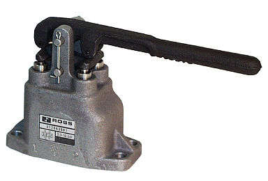
- Toggle Lever Valves
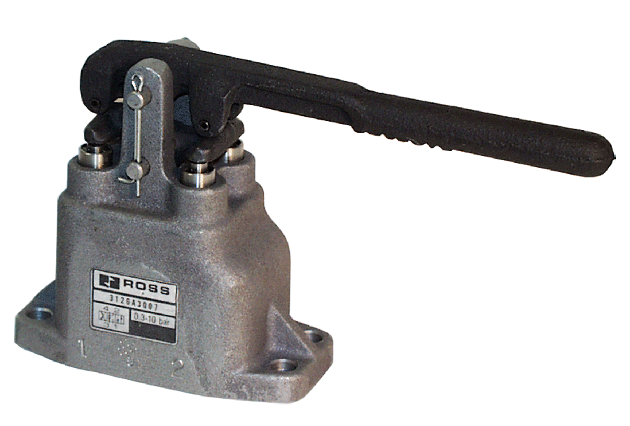
- Hand Lever Valves
Lever Valves 11, 31, & 36 Series Product Overview
ROSS mechanical valves are especially suited to serve as remote pilots to pass operating signals to other pressure actuated valves. Valves are widely used in automation for harnessing a mechanical action automatically to open or close and air circuit.
Please refer to the side and below for links to easily navigate and download ROSS Controls Lever Valves 11, 31, & 36 Series catalogs, installation instructions, and technical data. Additionally, you have the option to filter through all available options to Lever Valves 11, 31, & 36 Series variant that meets your requirements.
loading...
loading...
Product Overview
The ROSS Controls covers three distinct lever-actuated manual directional control valve families spanning from compact pilot-signal toggle levers through high-flow heavy-duty hand lever valves for direct cylinder and rotary actuator control. The breadth of this series allows a single product family to address lever-operated pneumatic control needs from 1/4 inch NPT pilot circuits to 1-1/4 inch NPT primary flow circuits with Cv values reaching 14.
The 11 Series Toggle Lever valve uses poppet construction with side and bottom mounting flanges to provide 2/2 and 3/2 normally closed functions at 1/4 inch ports with Cv 0.5. The glass-filled nylon lever knob and compact 1.82 by 2.76 by approximately 5.92 inch body make this the smallest lever-operated valve in the series, suited for pilot signal generation and machine-mounted interlock applications where the lever position is physically visible to the operator or maintenance technician.
The 36 Series Lever valve provides 3/2 and 4/2 normally closed functions in a mid-range poppet valve body with side and bottom mounting flanges, covering 1/4 inch ports with Cv 1.2. Available in both detented (maintained position) and spring return configurations, the 36 Series lever is used for machine-mounted directional control of single and double-acting cylinders where the lever provides a larger actuation arm than a pushbutton and the operator's hand can remain in contact with the lever for continuous modulated control.
The 31 Series Heavy-Duty Hand Lever valve is the high-capacity member of the series, providing 4/3 (four-way, three-position) direction with open-center or closed-center configurations. Available in horizontal lever and vertical lever orientations, port sizes from 3/8 to 1-1/4 inch, and Cv values from 1.7 to 14, the 31 Series serves as the primary manual directional control valve for large cylinder drives, rotary actuators, and air motor circuits. Detented and non-detented (spring return to center) variants cover both maintained and fail-to-center control requirements.
Key Engineering Features
- Three Lever Families Covering 1/4" to 1-1/4" Ports - The 11 Series toggle lever (1/4 inch, Cv 0.5), 36 Series lever (1/4 inch, Cv 1.2), and 31 Series heavy-duty hand lever (3/8 to 1-1/4 inch, Cv up to 14) provide full coverage from pilot circuit control through high-flow actuator direct drive in a single product family.
- Poppet Construction Across All Three Series - All Series lever valves use poppet valve internals for positive sealing, high dirt tolerance, and self-cleaning flow action. The poppet design eliminates the spool-based wear mechanisms and contamination sensitivity common in spool-type manual valves.
- 4/3 Three-Position Function in 31 Series - The 31 Series heavy-duty hand lever provides three-position 4-way control with open-center (connects all ports to each other in center position) and closed-center (blocks all ports in center position) configurations, enabling mid-stroke cylinder stopping and actuator holding without additional external valves.
- Detented and Spring Return Options (36 and 31 Series) - Both maintained-position (detented) and spring-return-to-default configurations are available in the 36 and 31 Series, supporting both latching directional control (operator sets direction and walks away) and safety-return-to-center (spring returns to center on release for fail-safe operation).
- Horizontal and Vertical Lever Orientations (31 Series) - The 31 Series heavy-duty hand lever is available with horizontal lever position (C1.8 models) and vertical lever position (C1.9 models), accommodating the full range of machine mounting orientations from panel-mounted vertical operators to machine-side horizontal operators.
- High Cv Ratings up to 14 in 31 Series - The largest 31 Series variant (1-1/4 inch ports, model 3126A7007/3126A7010) achieves Cv 14 in the main flow paths, enabling direct manual control of large bore cylinders and high-speed rotary actuators that would require separate pilot-operated valves in lower-Cv configurations.
- Side and Bottom Mounting Flanges - All Series lever valves include integrated side and bottom mounting flanges for direct machine frame mounting without separate brackets. The 11 Series flange pattern (0.34 inch diameter holes, 2.00 inch by 2.00 inch spacing) is shared with other 11 Series manual valves for consistent mounting layouts.
- Extended Temperature Range - The 11 Series toggle lever operates from -10F to 175F (-23C to 80C). The 36 Series lever valves operate from 40F to 175F (4C to 80C). The 31 Series heavy-duty hand lever operates from 40F to 175F (4C to 80C). Select the appropriate series for the operating environment temperature range.
- NPT and G Thread Options - All models are available in NPT threads as standard. G (BSPP) threaded variants are available by adding a D prefix to any model number (e.g., D3126A3007 for 31 Series with G threads).
- High-Flow Average Response Constants for System Design - Published average response constants F for fill and exhaust paths enable accurate system response time calculations using the formula Response Time (ms) = M + (F x V), where V is downstream volume in cubic inches, facilitating proper actuator sizing in time-critical applications.
Technical Specifications
General Specifications
| Parameter | Specification |
| Valve Families | 11 Series Toggle Lever; 36 Series Lever; 31 Series Heavy-Duty Hand Lever |
| 11 Series Toggle Lever Functions | 2/2 NC, 3/2 NC; Spring Return |
| 36 Series Lever Functions | 3/2 NC, 4/2 NC; Detented or Spring Return |
| 31 Series Hand Lever Functions | 4/3 (Open Center or Closed Center); Detented or Spring Return to Center |
| Construction (all series) | Poppet |
| Port Size - 11 Series | 1/4" NPT or G |
| Port Size - 36 Series | 1/4" NPT or G |
| Port Sizes - 31 Series | 3/8", 1/2", 3/4", 1", 1-1/4" NPT or G |
| Max Cv - 11 Series | 0.5 |
| Max Cv - 36 Series | 1.2 |
| Max Cv - 31 Series | 14 (Cv 1-2,4 paths, 1-1/4" port) |
| Operating Pressure (all) | 5 to 150 psig (0.3 to 10 bar) |
| Temperature - 11 Series | 10 to 175F (-23 to 80C) ambient and media |
| Temperature - 36 Series | 40 to 175F (4 to 80C) ambient and media |
| Temperature - 31 Series | 40 to 175F (4 to 80C) ambient and media |
| Flow Media | Filtered air |
| Valve Body Material | Die-cast aluminum |
| Lever Knob Material (11 Series) | Glass-filled nylon |
| Mounting | Side and bottom mounting flanges (all series) |
| Thread Types | NPT standard; G (BSPP) by D prefix |
Temperature Ratings
The 11 Series toggle lever poppet valves offer the widest temperature range in the series. The 36 and 31 Series poppet valves have a higher minimum operating temperature of 40F (4C). For temperatures below 40F (4C), supply air must be free of water vapor.
| Configuration | Ambient Temperature | Media Temperature |
| 11 Series Toggle Lever (Poppet) | 10 to 175F (-23 to 80C) | 10 to 175F (-23 to 80C) |
| 36 Series Lever (Poppet) | 40 to 175F (4 to 80C) | 40 to 175F (4 to 80C) |
| 31 Series Heavy-Duty Hand Lever (Poppet) | 40 to 175F (4 to 80C) | 40 to 175F (4 to 80C) |
Important: For media temperatures below 40F (4C), compressed air must be dry to prevent ice formation on poppet sealing surfaces. The 36 and 31 Series valves are not rated below 40F; the 11 Series toggle lever is rated to -10F (-23C).
Flow Performance Data
Flow performance data shown for representative models. Full model range includes horizontal (C1.8) and vertical lever (C1.9) orientations for 31 Series, and both detented and spring return for 36 Series. Response Time (ms) = M + (F x V). F values for 31 Series (3/8"-1/2" port): F(in-out) = 1.26, F(out-exhaust) = 1.43. Larger port sizes have lower F values as listed in the ROSS catalog.
| Series | Function | Port Size | Model | Cv | F 1-2 | F 2-3 | Weight lb (kg) |
| 11 Toggle Lever | 3/2 Spring Return | 1/4" | 1123A2002 | 0.5 | 2.5 | 3.2 | 1.0 (0.5) |
| 11 Toggle Lever | 2/2 Spring Return | 1/4" | 1121A2002 | 0.5 | 2.5 | N/A | 1.0 (0.5) |
| 36 Lever | 3/2 Detented | 1/4" | 3623A2003 | 1.2 | 1.66 | 1.43 | 1.3 (0.6) |
| 36 Lever | 3/2 Spring Return | 1/4" | 3623A2004 | 1.2 | 1.66 | 1.43 | 1.3 (0.6) |
| 36 Lever | 4/2 Detented | 1/4" | 3626A2003 | 1.2 | 1.66 | 1.43 | 2.5 (1.1) |
| 36 Lever | 4/2 Spring Return | 1/4" | 3626A2004 | 1.2 | 1.66 | 1.43 | 2.5 (1.1) |
| 31 Hand Lever | 4/3 Open Ctr, Horiz, Det | 3/8"-1/2" | 3126A3007 | 2.0 (0.9) | |||
| 31 Hand Lever | 4/3 Closed Ctr, Horiz, Det | 3/8"-1/2" | 3126A3010 | 2.0 (0.9) | |||
| 31 Hand Lever | 4/3 Open Ctr, Horiz, Det | 1/2"-3/4" | 3126A4007 | 3.8 (1.7) | |||
| 31 Hand Lever | 4/3 Open Ctr, Horiz, Det | 3/4"-1" | 3126A5007 | 5.0 (2.3) | |||
| 31 Hand Lever | 4/3 Open Ctr, Horiz, Det | 1"-1-1/4" | 3126A6007 | 10.0 (4.5) | |||
| 31 Hand Lever | 4/3 Open Ctr, Horiz, Det | 1-1/4"-1-1/2" | 3126A7007 | 11.0 (5.0) |
Certifications & Compliance
| Certification/Standard | Detail |
| Thread Standards | NPT standard on all models. G (BSPP, ISO 228-1) available by adding D prefix to model number (e.g., D3126A3007). |
| Temperature Verification | 11 Series rated -10F to 175F. 36 and 31 Series rated 40F to 175F. All ratings verified for both ambient and media conditions. |
| CAD Models | 2D and 3D CAD models available in multiple formats at rosscontrols.com for all Series variants. |
Typical Applications & Industries
Machine-Mounted Directional Control
- 11 Series toggle lever valves mounted directly on machine frames for operator-visible manual directional control of pilot circuits where the lever position provides immediate visual confirmation of the valve state without a panel indicator.
- 36 Series detented lever valves for set-and-forget directional control of single-acting and double-acting cylinders in fixtures and tooling where the operator sets the cylinder direction and then removes their hands from the lever during the work stroke.
- 36 Series spring-return lever valves for safety-return-to-default cylinder control applications where removing the operator's hand from the lever must automatically return the actuator to its safe position.
- Machine-mounted toggle levers as interlock confirmation devices where the lever position physically confirms a mechanical interlock condition, visible to both operator and maintenance personnel from the machine side.
High-Flow Cylinder and Actuator Direct Drive
- 31 Series heavy-duty hand lever valves for direct manual control of large bore cylinders (4 inch bore and above) where the high Cv values (up to 14) enable fast cylinder extension and retraction without the flow restriction limitations of smaller pilot valve circuits.
- Air motor start/stop and directional control in manufacturing and assembly applications where the 31 Series hand lever provides the operator with tactile feedback and positive mechanical control over motor direction without requiring electrical controls.
- Manual rotary actuator positioning in maintenance and commissioning applications where the engineer must drive large actuators slowly and precisely without relying on automated control systems.
- 4/3 closed-center configurations for cylinder hold and lock applications where the lever center position blocks all ports to prevent actuator drift under load without requiring a separate cylinder lock valve.
Remote Pilot Signal Generation
- 11 Series toggle lever valves as compact pilot signal sources for larger solenoid or air pilot directional control valves in complex pneumatic circuits requiring manual override capability without installing a large operator valve in the primary flow path.
- 36 Series lever valves as mid-flow pilot signal sources where downstream pilot-operated valves require more pilot flow volume than the 11 Series toggle lever can provide for fast response at high operating pressures.
- Panel-mounted 31 Series hand lever valves for manual circuit override in automated production systems, allowing maintenance engineers to drive actuators to safe positions for tooling change or maintenance without modifying the PLC control program.
Automation and General Industrial
- Metal fabrication and welding fixture controls where the 36 or 31 Series lever valves provide manual clamping and unclamping control for weld fixtures between automated welding cycles.
- Plastics processing and injection molding mold opening and closing auxiliary controls where the manual lever provides backup actuation capability during mold maintenance and changeover.
- Steel processing and heavy manufacturing environments where robust cast aluminum poppet valve construction withstands cutting fluid mist, grinding dust, and mechanical vibration over extended production periods.
Ordering and Model Number Configuration
The Series model numbers encode the valve series, function type, body size, and orientation (for 31 Series). Understanding the structure allows direct model number construction for standard configurations.
|
11 Series Toggle Lever Models: 1121A2002 2/2 NC Toggle Lever, 1/4" NPT, Spring Return, Cv 0.5 1123A2002 3/2 NC Toggle Lever, 1/4" NPT, Spring Return, Cv 0.5
36 Series Lever Models: 3623A2003 3/2 NC Lever, 1/4" NPT, Detented, Cv 1.2 3623A2004 3/2 NC Lever, 1/4" NPT, Spring Return, Cv 1.2 3626A2003 4/2 NC Lever, 1/4" NPT, Detented, Cv 1.2 3626A2004 4/2 NC Lever, 1/4" NPT, Spring Return, Cv 1.2
31 Series Heavy-Duty Hand Lever Models (Horizontal, C1.8): 3126A3007 4/3 Open Ctr, 3/8"-1/2" NPT, Detented, Cv 1.7/1.4 3126A3010 4/3 Closed Ctr, 3/8"-1/2" NPT, Detented, Cv 1.7/1.4 3126A4007 4/3 Open Ctr, 1/2"-3/4" NPT, Detented, Cv 2.8/2.3 3126A5007 4/3 Open Ctr, 3/4"-1" NPT, Detented, Cv 5.0/4.2 3126A6007 4/3 Open Ctr, 1"-1-1/4" NPT, Detented, Cv 10/7.5 3126A7007 4/3 Open Ctr, 1-1/4"-1-1/2" NPT, Detented, Cv 14/9.6
31 Series Heavy-Duty Hand Lever Models (Vertical, C1.9): 3126A3009 4/3 Open Ctr, 3/8"-1/2" NPT, Detented 3126A3012 4/3 Open Ctr, 3/8"-1/2" NPT, Non-Detented (Spring Center) 3126A3013 4/3 Closed Ctr, 3/8"-1/2" NPT, Detented 3126A3014 4/3 Closed Ctr, 3/8"-1/2" NPT, Non-Detented (Spring Center)
For G (BSPP) threads: add 'D' prefix to any model number. Example: D3126A5007 = 31 Series 3/4"-1" open center, G threads. |
Standard models ship with NPT threads. For G (BSPP) threads, add D prefix to the model number.
31 Series horizontal lever models (3126A_007 and 3126A_010 suffix) are for panel-top or machine-side mounting. Vertical lever models (3126A_009, _012, _013, _014 suffix) are for panel-face or machine-front mounting.
The 31 Series valve body accommodates two adjacent port sizes (e.g., 3/8 and 1/2 inch). The larger port size represents the exhaust port on these valves.
Open-center (suffix 007/009) connects all ports in the center lever position. Closed-center (suffix 010/013) blocks all ports in center position. Select based on actuator holding requirements.
Accessories
Exhaust Silencers
Aluminum exhaust silencers for 1/4 inch through 1-1/4 inch exhaust ports on Series lever valves. Silencer Cv must be equal to or greater than the valve exhaust Cv.
| Port Size | Thread | Cv | Model (NPT) | Model (G) |
| 1/4" | Male | 2.1 | 5500A2003 | D5500A2003 |
| 1/2" | Male | 6.8 | 5500A4003 | D5500A4003 |
| 1" | Male | 18 | 5500A6003 | D5500A6003 |
| 1-1/2" | Female | 39 | 5500A8001 | D5500A8001 |
Warning: Exhaust silencers must have flow capacity equal to or greater than the exhaust capacity of the valve. An undersized or contaminated silencer creates back pressure that can prevent the lever from fully shifting and may slow actuator return speed.
Related Products & Accessories
- Pedal and Treadle Valves (259 Series) - 36 and RM Series foot-operated poppet valves sharing the same 36 Series body as the series lever valves. https://www.rosscontrols.com/en/series/259-pedal-treadle-valves
- Palm and Push Button Valves (256 Series) - 11 and 12 Series manual pushbutton and palm button valves using the same 11 Series body as the series toggle lever. https://www.rosscontrols.com/en/series/256-palm-push-button-valves
- Cam and Plunger Valves (260 Series) - 11 Series mechanical cam roller and plunger valves sharing the same 11 Series body platform. https://www.rosscontrols.com/en/series/260-cam-plunger-valves
- Pendant Valves (255 Series) - 1 to 6 lever pendant control valve assemblies for material handling and overhead crane applications. https://www.rosscontrols.com/en/series/255-pendant-valves
- Exhaust Silencers - Aluminum silencers from 1/4 inch to 1-1/2 inch for Series lever valve exhaust ports. https://www.rosscontrols.com/en/series/90-silencers
Frequently Asked Questions (FAQ)
Q: What is the difference between the 11 Series toggle lever, 36 Series lever, and 31 Series hand lever?
A: The 11 Series toggle lever is the most compact, providing 2/2 or 3/2 functions at 1/4 inch ports with Cv 0.5 for pilot signal applications. The 36 Series lever provides 3/2 and 4/2 functions at 1/4 inch ports with Cv 1.2 for small cylinder direct drive and pilot use. The 31 Series heavy-duty hand lever is the largest family, providing 4/3 three-position functions in port sizes from 3/8 to 1-1/4 inch with Cv up to 14 for direct manual control of large actuators.
Q: What does open-center versus closed-center mean for the 31 Series 4/3 valve?
A: In the open-center configuration (model suffix 007 or 009), the center lever position connects all four ports together, allowing free-flow equalization and cylinder float under external load. In the closed-center configuration (suffix 010 or 013), the center position blocks all four ports, holding the cylinder position under both active load and spring force. Select open center for applications requiring free cylinder movement in center position; select closed center when the cylinder must hold position against an applied load when the lever is centered.
Q: Can I switch between detented and spring-return-to-center operation in the field?
A: No. The detented and spring-return-to-center configurations are different model numbers and cannot be field-converted between each other. Select the appropriate model at the time of ordering based on whether the application requires maintained position (detented) or automatic return to center position when the lever is released.
Q: What is the physical difference between horizontal and vertical lever models in the 31 Series?
A: Horizontal lever models (C1.8, suffix 007/010) have the hand lever oriented parallel to the valve mounting surface, suited for operators approaching the valve from the side or front. Vertical lever models (C1.9, suffix 009/012/013/014) have the lever oriented perpendicular to the mounting surface, suited for panel-face mounting where the operator reaches forward to actuate the lever. Both configurations have identical Cv ratings and internal dimensions.
Q: What is the response time formula for lever valves?
A: Response Time (ms) = M + (F x V). For manually operated lever valves, M (minimum response constant) is taken as zero in most practical applications since the response time is dominated by the operator actuation speed. F is the fill or exhaust factor for the specific flow path and port size, published in the ROSS catalog. V is the downstream volume in cubic inches to be filled to 90% of supply pressure or exhausted to 10%.
Q: Why are the 36 and 31 Series rated to only 40F minimum instead of -10F like the 11 Series?
A: The 11 Series uses a smaller poppet body optimized for the -10F to 175F range. The 36 and 31 Series valve bodies and seal materials are specified for the 40F to 175F range. For cold-temperature applications requiring lever actuation at temperatures below 40F (-40F to 40F range), consult ROSS for available low-temperature configurations or consider alternative series.
Q: Can the 31 Series handle hydraulic fluid or other liquids?
A: No. All Series lever valves are designed for filtered compressed air service only. They are not rated for hydraulic fluid, water, process gases, or other liquid or gas media. Using these valves with non-air media will damage seals and internal components.
Q: How do I calculate the required Cv for my cylinder application with a 31 Series hand lever valve?
A: Required Cv depends on cylinder bore diameter, stroke speed requirement, and supply pressure. A simplified approach: Cv = Q / (C x sqrt(deltaP x P2)), where Q is flow rate in SCFM, C is a constant (approximately 29 for air at standard conditions), deltaP is pressure drop across the valve, and P2 is downstream absolute pressure. ROSS application engineers can assist with accurate Cv calculations for specific actuator sizing requirements at (800) 438-7677.
Q: Are replacement lever assemblies and knobs available separately?
A: Contact ROSS Controls with the specific valve model number to identify available replacement lever assemblies, knobs, and service kits. Field-replaceable lever components are available for the major Series models to extend valve service life without complete valve replacement.
Q: What is the port layout for a 4/3 valve in the 31 Series?
A: Standard port assignments for 31 Series 4/3 valves: Port 1 is the pressure inlet, Port 2 and Port 4 are the cylinder ports (extend and retract), and Port 3 is the exhaust. In open-center position, all ports communicate. In the two shifted positions, the lever direction determines which cylinder port receives supply and which exhausts.
Q: Can two 31 Series valves be stacked or manifolded?
A: The 31 Series valves are designed for individual inline installation. They are not manifold-mount valves and do not have a sub-base or D03/D05 interface pattern. If manifold mounting of multiple hand-lever valves is required, consult ROSS for custom circuit designs or consider combining individual valves with a common inlet manifold block.
Q: What does the 31 Series designation mean relative to the 11 and 36 Series?
A: The ROSS series numbers designate distinct product families within the manual and mechanical valve catalog. The 11 Series is the smallest poppet valve body family (1/4 inch ports), the 36 Series is the mid-range body (1/4 inch ports, higher Cv), and the 31 Series is the heavy-duty larger body family (3/8 to 1-1/4 inch ports). The series numbers are product line identifiers, not indicators of performance ranking or generation.
Installation & Maintenance Guidelines
- Mount lever valves using the side or bottom mounting flanges with fasteners appropriate for the mounting surface. For the 31 Series heavy-duty hand lever valves, use fasteners rated for the expected operator actuation forces plus the weight of the valve assembly.
- Orient the lever to face the operator at an ergonomically appropriate height and angle. For 31 Series horizontal lever models, the lever extends laterally and requires adequate clearance for full stroke movement without contacting adjacent components or machine guards.
- Connect port 1 to the compressed air supply. For 3/2 and 4/3 configurations, port 2 (and port 4 on 4-way valves) connects to the actuator ports. Port 3 is the exhaust and should be connected to a silencer or routed to atmosphere away from operator positions.
- For 31 Series 4/3 valves, verify whether open-center or closed-center behavior is required before installation. The two variants have different internal orifice configurations that cannot be interchanged without replacing the valve.
- Supply filtered compressed air to the valve inlet. A 5-micron coalescing filter upstream of the lever valve is recommended. All Series lever valves use poppet construction and are more tolerant of moderate contamination than spool valves, but filtration is still required for maximum seal life.
- Do not exceed 150 psig (10 bar) supply pressure at port 1. Verify the upstream regulator setpoint before connecting the valve to the compressed air supply.
- For 36 Series and 31 Series spring-return lever valves, verify that the lever returns fully to the default position when released. A sticky lever that fails to return fully indicates a blocked exhaust port, a contaminated poppet, or a damaged spring.
- For 31 Series detented lever valves, verify that both detent positions engage positively and that the lever does not slip between positions under vibration or normal production conditions. A lever that does not hold position in detented models may indicate worn detent springs or damaged detent mechanism.
- After installation, perform a full-stroke lever actuation cycle and verify cylinder or actuator movement in both directions and return to center (for 4/3 valves). Check all port connections for leakage with a leak detection solution.
- For 11 Series toggle lever valves used as pilot signal sources, ensure that the downstream pilot-operated valve has a pilot pressure minimum requirement below the system supply pressure, and that the pilot supply tubing volume is minimized to ensure fast pilot signal propagation.
- Do not use the lever as a handle for lifting or carrying the valve or the machine assembly. Lever forces should be limited to the designed actuation range. Excessive lever side-loading can damage the lever shaft and poppet alignment.
- Inspect lever pivot points, return springs, and detent mechanisms during scheduled maintenance intervals. Lubricate lever pivot points with a small amount of petroleum-based grease as needed to maintain smooth lever actuation without stiffness that could lead to operator injury or fatigue.
Warranty & Global Support
ROSS Controls provides a one-year warranty on all Series lever valves, covering defects in material and workmanship from the date of purchase.
Technical support is available through ROSS Controls USA at (800) 438-7677 or through ROSS global offices in Canada, Brazil, Germany, France, United Kingdom, India, China, and Japan.
Service kits with replacement seals, poppets, and springs are available from ROSS for field refurbishment of all Series valve families.
For dimensional drawings, CAD models, and complete technical specifications including port layouts and mounting dimensions, visit the ROSS Controls product page at rosscontrols.com or contact your authorized ROSS distributor.
Product Catalog - Manual Toggle/Lever Valves: https://www.rosscontrols.com/en/documents/3887?filename=Manual_Toggle_Lever_Valves_ROSS-MV_TL_EN.pdf
Installation Instructions - 11 & 12 Series: https://www.rosscontrols.com/en/documents/52?filename=ROSS_11_12_Series_Mechanical_and_Manual_Valves_Installation_Instructions_SS105.pdf
Installation Instructions - 31 & 36 Series: https://www.rosscontrols.com/en/documents/53?filename=ROSS_31_36_Series_Manual_Valves_Installation_Instructions_SS104.pdf
Download Documents
Lever Valves