HDBH HDBH Series
- Each single valve in the HDBH Series system is equipped with an inductive position switch.
- Monitoring of these switches is to be done by an electrical safety control system.
- Redundant spool type valve system.
- Special tamper resistant tool required for disassembly.
- Mounts between manifold and directional valve.
- Flow doubling available in applications where higher flows are needed.
- Spacer kits are available to avoid interference with other devices on the manifold.
Hydraulic Dual Block and Stop Valves HDBH Series Product Overview
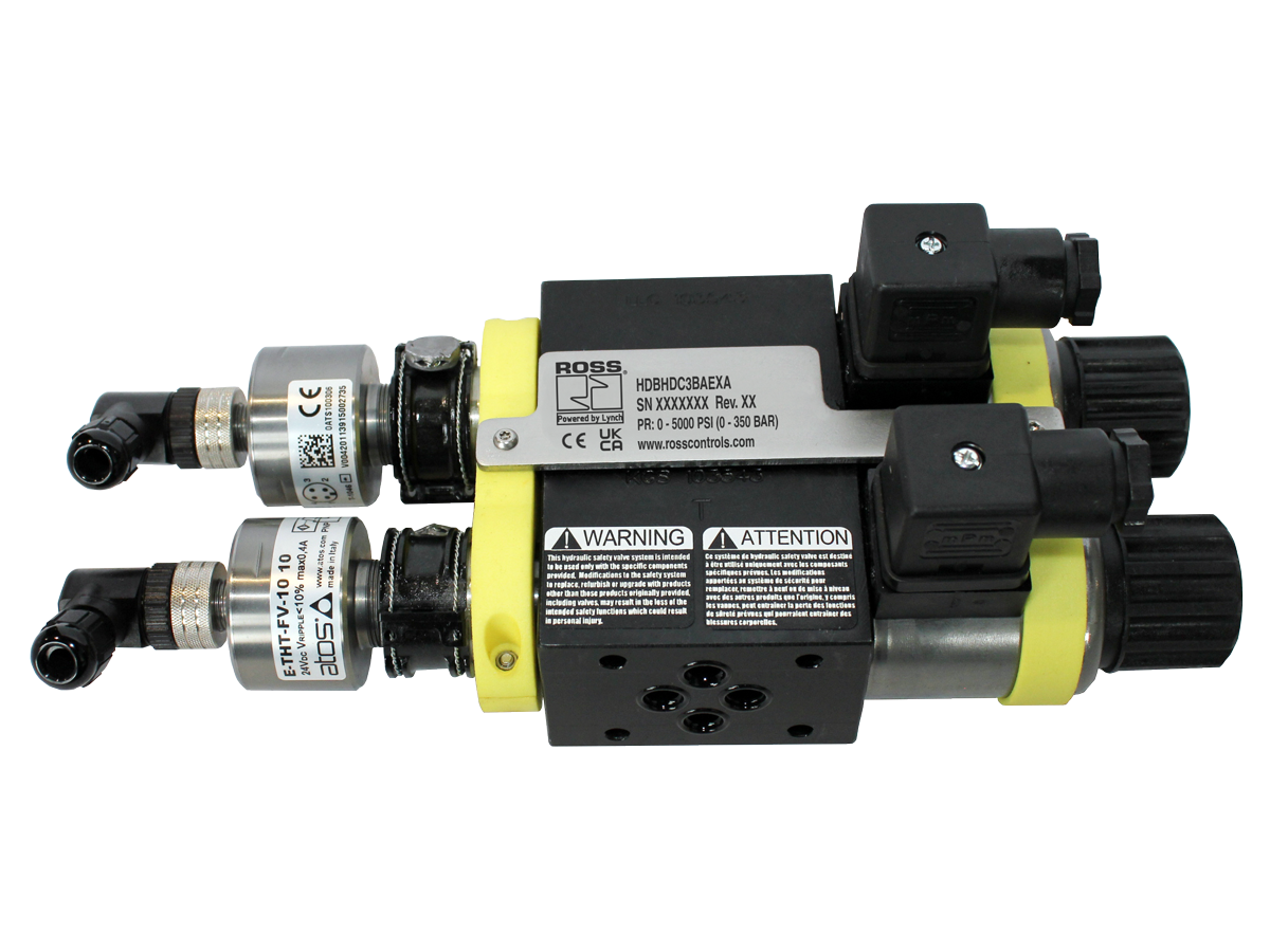
The HDBH Series system is a redundant, dual blocking valve system designed for critical applications where safe stopping is required for hydraulically controlled actuators. This valve system is equipped with inductive position switches for external monitoring by an electrical safety control system. The HDBH valve is designed to be sandwich-style mounted (interposed) between a manifold and a directional valve, or in-line mounted by use of optional mounting kits.
Block and Stop functions are intended to momentarily stop an actuator (linear or rotary), but not to hold the actuator in place for an extended period. The HDBH valve is a spool type valve, and normal spool leakage will occur. The valve is intended to be used as a “permissive” safety device. Applications where long-term holding is necessary should also incorporate other components such as PO check, counterbalance, or mechanical locking devices.
HDBH valves are intended to be used only for tasks that are routine, repetitive, and integral to production. Maintenance tasks require following full lock-out/tag-out procedures to relieve hazardous energy and prevent unexpected startup.
Please refer to the side and below for links to easily navigate and download ROSS Controls Hydraulic Dual Block and Stop Valves HDBH Series catalogs, installation instructions, and technical data. Additionally, you have the option to filter through all available options to Hydraulic Dual Block and Stop Valves HDBH Series variant that meets your requirements.
loading...
loading...
Product Overview
The ROSS Controls HDBH Series is a redundant, dual blocking valve system designed for critical applications where safe stopping is required for hydraulically controlled actuators. This system is uniquely designed to mount as a sandwich (interposed) plate between an ISO 4401 size 06 (D03) manifold and a directional control valve, providing a space-efficient means of adding dual block and stop safety capability to existing or new D03 directional valve stations without requiring a separate inline valve or additional plumbing.
The HDBH system contains two independent 4/2 spool-type valve elements, each with a single solenoid and spring return. Both solenoids must be energized together to allow hydraulic flow from the directional valve to the actuator. When either or both solenoids are de-energized, both valve elements immediately shift to the spring-return (blocked) position, stopping the actuator. Each valve element is equipped with a PNP inductive position switch for external monitoring by an electrical safety control system.
The Block and Stop function of the HDBH is designed to momentarily stop an actuator (linear or rotary) and not to hold the actuator in place for an extended period. The HDBH is a spool-type valve, and normal spool leakage will occur. For applications where sustained load holding is required, additional components such as pilot-operated check valves, counterbalance valves, or mechanical locking devices must be incorporated. The HDBH is intended as a permissive safety device used in routine, repetitive production tasks.
The HDBH Series provides flow doubling capability for applications requiring higher actuator flow than a single D03 valve path can supply: two HDBH units can be installed in parallel on adjacent manifold stations to double the effective flow capacity. Spacer kits are also available to provide clearance for other components already mounted on the manifold, allowing the HDBH to be added to existing manifold assemblies without requiring manifold modification.
Key Engineering Features
- Sandwich-Mount (Interposed) Design - Installs between any ISO 4401 size 06 (D03 footprint) manifold and directional control valve using standard D03 mounting hardware. No additional plumbing or manifold modification required, enabling safe stop capability to be added to existing D03 valve stations on new and retrofit machines.
- Redundant Dual 4/2 Valve Architecture - Two independent 4/2 spool valve elements, each with its own solenoid and spring return. Both must be energized to permit flow. De-energization of either element stops the actuator, providing the redundancy required for external safety monitoring architectures.
- PNP Inductive Position Switches - One PNP inductive position switch per valve element (M12 5-pin A-coded, 2 per system) continuously monitors spool position. An external electrical safety control system monitors both switch states to detect valve discrepancies and fault conditions.
- Flow Doubling Capability - Two HDBH units installed in parallel on adjacent D03 manifold stations effectively double the flow capacity from 5 gpm to 10 gpm per actuator port pair. This enables application on larger D03-ported actuators without requiring an upsized directional valve manifold.
- Spacer Kits for Interference Avoidance - Optional ductile iron spacer kits in 0.75 in (19.1 mm) and 1.75 in (44.5 mm) heights (models 2548B25 and 2549B25) provide clearance between the HDBH valve and adjacent components on the manifold such as speed controls or check valves.
- High MTTFd Reliability - Published functional safety data includes MTTFd (Mean Time to Dangerous Failure) of 150 years, providing the quantitative reliability data required for ISO 13849-1 and IEC 61508 safety integrity calculations.
- Direct Solenoid Actuation - Both D03 valve elements use direct solenoid actuation for fast, consistent response. Direct actuation eliminates the pilot pressure dependency of pilot-operated designs, ensuring reliable shifting across the full operating pressure range including at low pressure.
- Tamper-Resistant Assembly - Tamper-resistant bracket and fastener system requires a special tool for disassembly, maintaining the integrity of the safety valve configuration and preventing unauthorized removal or modification of the interposed safety device.
- Cast Steel Body for Manifold Compatibility - Valve body constructed from cast steel to match the mechanical properties of ductile iron D03 manifolds, ensuring proper bolt pre-load retention and long-term sealing at the manifold-to-valve interface.
- Buna-N Seals with Extended Ambient Temperature - Buna-N seals provide compatibility with standard hydraulic fluids and an extended ambient temperature range of -22 to 160 F (-30 to 70 C), wider than other HBB/HBH series, accommodating cold-environment applications.
Technical Specifications
General Specifications
| Parameter | Specification |
| Safety Function | Dual Block & Stop |
| Valve Type | Directional Control |
| Construction | Redundant Spool Type |
| ISO Size | D03 (ISO 4401 size 06) |
| Valve Function | Dual 4/2 Single Solenoid, Spring Return |
| Actuation | Direct Solenoid Operated, Spring Return |
| Mounting | Sandwich-style (interposed) between D03 manifold and directional valve; optional inline with mounting kits |
| Monitoring | External (by electrical safety control system) |
| Standard Voltage | 24 VDC |
| Duty Cycle | Continuous Duty |
| Power Consumption (each solenoid) | 30 watts |
| Solenoid Connection Type | EN 175301-803 Form A |
| Solenoid Enclosure Rating | IP65 per DIN 40050 |
| Inductive Position Switch Type | PNP, M12 5-pin A-coded (2 per system) |
| Switch Current Consumption (Max) | 400 mA per switch |
| Flow Rate | 5 to 10 gpm (flow doubling: up to 10 gpm per port pair with two parallel units) |
| Operating Pressure - Ports P, A, B (Max) | 5000 psi (344 bar) |
| Operating Pressure - Port T (Max) | 3000 psi (210 bar) |
| Flow Media | Mineral Oil HLP, HL-DIN 51524; Vegetable Oil HETG - VMDA 24568 |
| Valve Body & Manifold Material | Cast Steel |
| Spool Material | Steel |
| Seal Material | Buna-N |
| MTTFd | 150 years |
| Length | 10.0 in (255 mm) |
| Width | 3.9 in (100 mm) |
| Height | 3.4 in (87 mm) |
| Weight | 15.0 lb (6.80 kg) |
Temperature Ratings
HDBH Series has a wider ambient temperature range than other HBB/HBH series due to the cast steel construction and Buna-N seal compound used.
| Configuration | Ambient Temperature | Media Temperature |
| Ambient Temperature | 22 to 160 F (-30 to 70 C) | |
| Media (Hydraulic Fluid) Temperature | 4 to 140 F (-20 to 60 C) |
Important: Maintain hydraulic fluid viscosity within the design range across the full temperature envelope. At cold-ambient startup, allow fluid to warm above -4 F (-20 C) before demanding full valve actuation speed.
Certifications & Compliance
| Certification/Standard | Detail |
| Functional Safety Data | MTTFd (Mean Time to Dangerous Failure): 150 years. This value is used in ISO 13849-1 Category and PL calculations and IEC 61508 SIL calculations for the overall safety system. |
| Safety Architecture | Designed for external monitoring. When integrated with a Category 4 / PL e rated external safety control system, enables the highest machine safety performance levels per ISO 13849-1 and IEC 61508. Certifications pending on specific configurations. |
| Solenoid Standard | Solenoids conform to VDE 0580 for continuous duty rated coils in industrial hydraulic applications. |
| Solenoid Enclosure | IP65 per DIN 40050, providing dust-tight protection and resistance to low-pressure water jets in industrial environments. |
| Position Switch Standard | Inductive position switches conform to EN 60947-5-2 for proximity switches used in safety-related applications. |
| ISO Footprint Compliance | D03 manifold footprint compliant with ISO 4401 size 06, ensuring dimensional compatibility with all standard D03 directional valve manifolds from major hydraulic component manufacturers. |
Typical Applications & Industries
Hydraulic Cylinder Actuated Machinery
- D03 directional valve stations on hydraulic machinery where a safety stop capability must be added between the directional valve and actuator without significant machine redesign. The sandwich mount enables retrofit installation with minimal downtime.
- Clamping cylinder circuits on machining centers where the clamping must be safely stopped and the workpiece held before tool change access, using the HDBH as a permissive interlock between the directional valve and clamp cylinder.
- Feed axis cylinder circuits on hydraulic broaching or honing machines, where the HDBH provides safe stop of the feed cylinder before dressing or tool change operations.
Plastic Injection Molding
- Injection unit advance and retraction circuits on D03-ported directional valves, adding safe stop between production cycles when the injection barrel must be accessed for purging or nozzle maintenance.
- Ejector pin cylinder circuits requiring safe stop before mold open access. The HDBH interposes between the ejector directional valve and the ejector cylinder, providing the dual block safety function.
- Core pull and side action cylinder circuits on injection molds where the HDBH prevents unintended core movement during mold opening, protecting tooling and operators.
Assembly and Test Equipment
- Hydraulic press and assembly fixture circuits on D03 valve stations where safe stop is required between production cycles for part loading and unloading.
- Hydraulic test bench actuator circuits where the HDBH provides dual block stop between test sequences when test fixtures are accessed for part change.
- Hydraulic rotary index table drive circuits where the HDBH provides safe stop at each index position before robotic or manual access to the work zone.
Material Handling and Conveyance
- Hydraulic tipping and tilting table circuits in material handling systems, where the HDBH provides safe stop before personnel access to the tipped-load area.
- Hydraulic cylinder circuits on automated guided vehicles (AGV) and material transfer carts, where D03 directional valves control lift and tilt functions requiring safe stop at maintenance positions.
- Conveyor diverter and gate hydraulic actuator circuits where safe stop is required before lane access or jam clearing procedures.
Mobile and Industrial Hydraulics
- D03 valve station circuits on industrial machinery where dual block stop capability must be added to a standard directional valve without replacing the manifold, using the spacer kit option to accommodate existing accessory components.
- Hydraulic actuator circuits in cold environments operating down to -22 F (-30 C), where the HDBH wider temperature range supports outdoor and refrigerated facility applications.
- Redundant safety stop for hydraulic actuators on robotic end-of-arm tooling where the D03 footprint and compact dimensions enable integration within robot arm assembly envelopes.
Metal Cutting and Forming
- Hydraulic cylinder circuits on CNC turning and machining centers with D03 manifolds, providing dual block stop for tailstock, steady rest, or part loading cylinder circuits.
- Hydraulic clamping circuits on transfer line fixtures where D03 directional valves control multiple clamp cylinders and the HDBH provides safe stop for each station independently.
- Hydraulic turret index and clamp cylinder circuits on CNC lathes, where the HDBH provides safe stop before manual access to change toolholders or clear chips.
Ordering and Model Number Configuration
The HDBH Series has a single standard model configuration: HDBHDC3BAEXA. This model covers the D03 sandwich-mount dual block and stop function in the standard configuration. Contact ROSS Controls for special configurations.
|
HDBH Series Model Number Structure:
HDBH D C3 B A E X A | | Series | | | Revision Level | | Communication (X = None) | Monitoring (E = External) | Seal Type (A = Buna-N) Valve Type (B = Double) Body Size (C3 = D03) Voltage (D = 24 VDC)
Standard Model: HDBHDC3BAEXA
Spacer Kit Models: 2548B25 = 0.75 in (19.1 mm) ductile iron spacer 2549B25 = 1.75 in (44.5 mm) ductile iron spacer |
Standard model HDBHDC3BAEXA is the only listed production configuration. Contact ROSS Controls for any application requiring configurations outside this standard.
Spacer kits (models 2548B25 and 2549B25) are ordered separately from the HDBH valve. Select spacer height based on the clearance required over adjacent manifold-mounted components.
For flow requirements above 5-10 gpm per actuator port pair, two HDBH units can be installed in parallel on adjacent D03 manifold stations to provide flow doubling.
For inline mounting rather than sandwich mounting, contact ROSS Controls for optional inline mounting kit availability and configuration.
Accessories
Spacer Kits for Manifold Interference Avoidance
Ductile iron spacer kits provide additional clearance between the HDBH valve and other components mounted on the directional valve manifold. Order separately from the HDBH valve.
| Spacer Type | Height | Model Number |
| Ductile Iron | 0.75 in (19.1 mm) | 2548B25 |
| Ductile Iron | 1.75 in (44.5 mm) | 2549B25 |
Electrical Connectors for Solenoids
EN 175301-803 Form A prewired connectors compatible with the HDBH Series 24 VDC solenoids. Available in standard and lighted configurations.
| Connection | Cord Length | Model (No Light) | Model (24 VDC Lighted) |
| EN 175301-803 Form A Prewired (18 AWG) | 2 m (6.5 ft) | 721K77 | 720K77-W |
| EN 175301-803 Form A Prewired (18 AWG) | 2 m (6.5 ft) | 371K77 | 383K77-W |
| Connector Only (no cord) | 937K87 | 936K87-W |
Warning: Do not use surge suppressor connectors. Surge suppressors delay solenoid de-energization and increase the time required for the HDBH to reach the safe (blocked) state.
Related Products & Accessories
- HBB Series Hydraulic Block & Bleed Valves - Redundant 3/2 hydraulic block and bleed valve systems in D03, D05, and D07 body sizes for circuits requiring downstream pressure venting. https://www.rosscontrols.com/en/series/1311-hbb
- HBH Series Hydraulic Block & Stop Valves - High-flow redundant block and stop valve systems for D25 and D32 body sizes with poppet-type cartridge elements for positive load holding up to 145 gpm. https://www.rosscontrols.com/en/series/1312-hbh
- Hydraulic L-O-X Lockout Valve - Manual hydraulic lockout valve for OSHA-compliant energy isolation before maintenance tasks, with bypass and downstream bleed capability. https://www.rosscontrols.com/en/series/3133-hydraulic-lockout-valve
- ElectroGuard Energy Isolation System - Complete integrated electrical, pneumatic, and hydraulic energy isolation system with remote lockout stations certified to Category 4 / PL e. https://www.rosscontrols.com/en/series/1314-electroguard
- DM2 Series Pneumatic Double Valves - Control-reliable pneumatic double valves for Category 4 / PL e safe exhaust applications in machine guarding, complementing hydraulic safety circuits. https://www.rosscontrols.com/en/categories/529-hydraulic
Frequently Asked Questions (FAQ)
Q: What does sandwich-mount (interposed) mean?
A: Sandwich mounting means the HDBH valve installs between two existing components: the D03 hydraulic manifold on the bottom and the directional control valve on top. The HDBH valve body has a D03 footprint on both its manifold face and its directional valve face, allowing it to be inserted into an existing valve station using the same manifold bolt pattern. No additional tubing, fittings, or manifold machining is required.
Q: What is the Block and Stop safety function?
A: Block and Stop means the valve blocks hydraulic flow in both directions simultaneously, stopping actuator motion immediately when de-energized. Unlike Block and Bleed, the downstream actuator circuit is not vented to tank. The actuator stops and holds its position (with the caveat that spool-type valves have inherent leakage, so long-term holding requires additional devices).
Q: Is the HDBH suitable for permanent load holding?
A: No. The HDBH uses spool-type valve elements, which have inherent internal leakage. It is designed to stop an actuator momentarily as a permissive safety device, not to hold a load indefinitely. For sustained load holding, pilot-operated check valves, counterbalance valves, or mechanical locking devices must be incorporated downstream of the HDBH.
Q: What is the MTTFd of the HDBH Series?
A: The published MTTFd (Mean Time to Dangerous Failure) is 150 years. This is a key parameter in ISO 13849-1 Category and Performance Level calculations. The high MTTFd value reflects the robust design and conservative application of the HDBH as a dual-redundant safety system.
Q: What flow rate is the HDBH rated for?
A: The standard HDBH is rated for 5 to 10 gpm. For applications requiring higher flow, two HDBH units can be mounted in parallel on adjacent D03 manifold stations to double the effective flow capacity.
Q: Can the HDBH be used on any D03 directional valve manifold?
A: Yes. The HDBH D03 footprint is compliant with ISO 4401 size 06, which is the standard footprint used by all major hydraulic component manufacturers for their D03 directional valve manifolds. The standard bolt pattern and port locations on both faces of the HDBH are compatible with ISO 4401 size 06 manifolds and directional valves.
Q: What is the purpose of the spacer kits?
A: Spacer kits add vertical clearance between the HDBH valve and adjacent components already mounted on the directional valve manifold. For example, if speed control valves or check valves are installed next to the target D03 station, a spacer kit raises the HDBH above those components, preventing interference. Spacer kits are available in 0.75 in and 1.75 in heights.
Q: Can the HDBH be mounted inline rather than as a sandwich plate?
A: The primary design intent is sandwich mounting. Optional inline mounting kits may be available. Contact ROSS Controls for inline mounting configurations and kit availability.
Q: What are the port pressure ratings?
A: Ports P, A, and B are rated to 5000 psi (344 bar) maximum. Port T (tank return) is rated to 3000 psi (210 bar) maximum. Systems with high tank line back-pressure must ensure tank line pressure does not exceed 3000 psi at the HDBH tank port.
Q: How does the HDBH differ from the HBB and HBH series?
A: The HDBH is specifically designed for sandwich mounting between a D03 manifold and directional valve, targeting individual actuator circuit level safety stops. The HBB (Block and Bleed) and HBH (Block and Hold) series are inline-mounted systems for larger flow rates (up to 145 gpm) and are typically used at the machine zone or main supply circuit level rather than at individual directional valve stations.
Q: How is the ambient temperature range different from the HBB and HBH series?
A: The HDBH has an ambient temperature range of -22 to 160 F (-30 to 70 C), which is wider at the low end than the HBB and HBH series (-4 to 160 F). This extended low-temperature capability makes the HDBH suitable for cold-environment or outdoor applications.
Q: What wiring is required for the position switches?
A: Each position switch uses an M12 5-pin A-coded connector. Pin 1 = +24 VDC, Pin 3 = Ground, Pin 2 = NC output, Pin 4 = NO output. The external safety controller must monitor both NO and NC outputs for each switch and detect cross-faults, short circuits, and discrepancies between the two switches within the safety function response time requirement.
Installation & Maintenance Guidelines
- Confirm the target manifold has a standard ISO 4401 size 06 (D03) port pattern before ordering. The HDBH bolt holes must align with the manifold's D03 bolt circle.
- If adjacent manifold-mounted components are present, measure the clearance height required before selecting a spacer kit. Model 2548B25 adds 0.75 in clearance; model 2549B25 adds 1.75 in.
- For flow doubling, install two HDBH units on adjacent D03 manifold stations and parallel the A and B port connections at the actuator. Both HDBH pairs must be controlled synchronously by the safety system.
- Wire both solenoids for synchronous operation using a safety-rated dual-channel output module. Never energize one solenoid independently.
- Wire both PNP inductive position switches to the external safety PLC or safety relay. Program the safety controller to detect discrepancies between the two switch states within the required safety response time.
- Verify all D03 manifold mounting bolts are torqued to the manifold manufacturer's specification. Uneven bolt loading can distort the HDBH-to-manifold interface and cause internal or external leakage.
- Maintain hydraulic fluid cleanliness at ISO 4406 Class 16/14/11 or better to prevent spool sticking and position switch interference.
- Do not use surge suppressor connectors on solenoid connections. Surge suppressors extend de-energization time and increase safety function response time.
- After installation, verify valve function by cycling both solenoids independently and confirming that each position switch changes state correctly before integrating into the machine safety control system.
- Document the HDBH installation location, manifold assembly, and safety system integration parameters in the machine safety file for compliance with ISO 12100 and the Machinery Directive.
Warranty & Global Support
ROSS Controls provides a one-year warranty on all products, covering defects in material and workmanship from the date of purchase.
Global technical support is available through ROSS Controls offices in the USA (headquarters in Ferndale, Michigan), Canada, Brazil, Germany, France, United Kingdom, India, China, and Japan.
Contact ROSS Controls USA at +1-248-764-1800 or (800) 438-7677, or visit rosscontrols.com for product configuration, application engineering support, functional safety data, and distributor locator services.
MTTFd and other functional safety data (diagnostic coverage, CCF parameters) for ISO 13849-1 and IEC 61508 calculations are available upon request for all HDBH Series configurations.
Download Catalog: https://www.rosscontrols.com/en/series/1313-hdbh
Download Documents
HDBH
