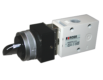
Selector Switch Valves 12 Series

- 3/2 inline, spool & sleeve valve
- Black switch knob actuator
- Normally Close, or Normally Open operations simply by piping the inlet supply accordingly
Selector Switch Valves 12 Series Product Overview
ROSS manual selector switch valve is actuated by turning the selector switch ON, and de-actuated by turning the switch OFF. The valve actuator must be held in actuated position to keep valve shifted. By turning the selector switch OFF, the valve resumes its normal position.
Please refer to the side and below for links to easily navigate and download ROSS Controls Selector Switch Valves 12 Series catalogs, installation instructions, and technical data. Additionally, you have the option to filter through all available options to discover Selector Switch Valves 12 Series variant that meets your requirements.
loading...
loading...
Product Overview
The ROSS Controls Selector Switch Valves are 12 Series spool and sleeve directional control valves with a detented black switch knob actuator, designed for applications requiring maintained manual selection of pneumatic circuit states. Unlike spring-return pushbutton valves that return to their default position when released, the selector switch valve holds its shifted position until the operator actively turns the knob to the opposing position, making it suitable for mode selection, circuit bypass, and maintained function switching in pneumatic control panels.
The 12 Series spool and sleeve construction provides a compact inline body measuring 1.46 by 4.6 by 1.26 inches (37 by 118 by 32 mm) in a 3/2 configuration with 1/8 or 1/4 inch NPT or G ports. The black switch knob actuator rotates between two detented positions, providing positive tactile feedback confirming that the valve is fully shifted to the selected state. This detenting mechanism prevents ambiguous mid-position states that could result in unintended partial flow conditions.
The valve achieves normally closed or normally open circuit function simply by routing the compressed air inlet supply to the appropriate port, eliminating the need to stock two separate model numbers for NC and NO applications. Cv ratings of 0.6 at 1/8 inch ports and 0.9 at 1/4 inch ports support pilot signal generation and small actuator control applications. The spool and sleeve construction shares the same material platform as the 12 Series pushbutton family, including stainless steel and polyoxymethylene switch parts and glass-filled nylon switch components.
For design engineers specifying pneumatic control panels, the series provides a self-maintaining pneumatic selector function with the same 12 Series compact body envelope as the pushbutton variants, simplifying panel layout and allowing mixed use of pushbutton and selector switch valves in the same mounting footprint.
Key Engineering Features
- Detented Switch Knob Actuation - The black switch knob turns between two positive detent positions, holding the valve in the selected state without the operator maintaining hand force. This is the critical differentiator from spring-return pushbutton valves and makes the selector switch suitable for maintained circuit mode selection.
- NC or NO Function by Piping - Normally closed and normally open circuit functions are achieved by selecting which port receives the compressed air supply inlet, not by changing the valve model. This eliminates the need for two separate part numbers for NC and NO applications of the same valve.
- Spool and Sleeve Construction - The 12 Series spool and sleeve construction provides a compact inline body that fits standard panel cutout sizes and is compatible with the same mounting footprint as the 12 Series flush and mushroom pushbutton variants, allowing mixed function panels with consistent dimensions.
- Compact 12 Series Body Envelope - The selector switch valve body measures 1.46 inches (37 mm) length by 4.6 inches (118 mm) width by 1.26 inches (32 mm) height, enabling dense panel layouts where multiple circuit selection switches must fit within a limited panel area.
- High-Quality Switch Materials - Switch components are manufactured from stainless steel, polyoxymethylene (POM), and glass-filled nylon, providing corrosion resistance and dimensional stability across the 40F to 175F operating temperature range.
- Valid and Invalid Operation Zones - The 12 Series design specifies a valid operation distance of 0.22 inches (5.5 mm) and an invalid operation distance of 0.04 inches (1.0 mm) with a required actuation force of 7.7 lb (3.5 kg). These parameters define the clear engagement threshold that prevents inadvertent partial actuation.
- NPT and G Thread Options - Standard models include NPT threads. G (BSPP) threaded variants are available by adding a D prefix to any model number (e.g., D1223B1SLB for 1/8 inch G threads), enabling direct use in metric pneumatic systems without adapters.
- Black Switch Knob Standard Actuator - The single standard actuator color for the series is black (suffix SLB), consistent with the convention for selector-type controls in industrial panel design per ANSI/NFPA 79 guidelines where black or gray indicates a selector or mode switch rather than a start or stop function.
Technical Specifications
General Specifications
| Parameter | Specification |
| Series | 12 |
| Valve Function | 3/2 (Normally Closed or Normally Open by piping) |
| Construction | Spool and Sleeve |
| Actuation | Manual Selector Switch (detented) |
| Return | Detented (maintained position) |
| Port Sizes | 1/8" and 1/4" NPT or G |
| Maximum Cv (1/8" port) | 0.6 |
| Maximum Cv (1/4" port) | 0.9 |
| Operating Pressure | 5 to 150 psig (0.3 to 10 bar) |
| Ambient Temperature | 40 to 175F (4 to 80C) |
| Media Temperature | 40 to 175F (4 to 80C) |
| Flow Media | Filtered air |
| Valve Body Material | Die-cast aluminum |
| Spool Material | Aluminum |
| Seal Material | Nitrile rubber |
| Spring Material | Stainless steel |
| Switch/Knob Materials | Stainless steel, polyoxymethylene, glass-filled nylon |
| Switch Knob Color | Black |
| Valid Operation Distance | 0.22 inches (5.5 mm) |
| Invalid Operation Distance | 0.04 inches (1.0 mm) |
| Actuation Force (valid/invalid threshold) | 7.7 lb (3.5 kg) |
| Mounting | Inline |
| Thread Types | NPT standard; G (BSPP) by D prefix |
| Dimensions (L x W x H) | 1.46 x 4.6 x 1.26 in (37 x 118 x 32 mm) |
| Weight (1/8" port) | 0.31 lb (0.14 kg) |
| Weight (1/4" port) | 0.37 lb (0.17 kg) |
Temperature Ratings
The 12 Series spool and sleeve construction has a minimum operating temperature of 40F (4C) due to the close-fitting aluminum spool and sleeve geometry. For applications requiring operation below 40F, consider the poppet-based 11 Series manual valves which operate to -10F (-23C).
| Configuration | Ambient Temperature | Media Temperature |
| 12 Series Selector Switch (all models) | 40 to 175F (4 to 80C) | 40 to 175F (4 to 80C) |
Important: For media temperatures below 40F (4C), compressed air must be free of water vapor to prevent ice formation inside the spool bore. The 12 Series spool construction is not rated for operation below 40F.
Flow Performance Data
Cv values are average flow coefficients at rated conditions. Response time for manually actuated selector switch valves follows the formula Response Time (ms) = M + (F x V) where M is taken as zero for manual actuation and V is downstream volume in cubic inches.
| Valve Type | Port Size | Model | Cv | Weight lb (kg) |
| 3/2 Selector Switch, Detented | 1/8" | 1223B1SLB | 0.6 | 0.31 (0.14) |
| 3/2 Selector Switch, Detented | 1/4" | 1223B2SLB | 0.9 | 0.37 (0.17) |
Certifications & Compliance
| Certification/Standard | Detail |
| Thread Standards | NPT standard on all models. G (BSPP, ISO 228-1) available by adding D prefix to model number (e.g., D1223B1SLB). |
| Actuator Color Convention | Black switch knob conforms to industrial panel color coding conventions per ANSI/NFPA 79, indicating a selector or mode switch rather than a start (green) or stop (red) function. |
| CAD Models | 2D and 3D CAD models available for download in multiple formats at rosscontrols.com for all Series variants. |
Typical Applications & Industries
Pneumatic Circuit Mode Selection and Bypass
- Manual mode/auto mode selection in pneumatic control circuits where the selector switch shifts the air circuit between manual operator control and automatic machine-cycle control without interrupting downstream equipment.
- Circuit bypass and isolation for maintenance and commissioning, where the selector switch routes supply air around a section of the pneumatic circuit to allow testing of downstream components while bypassing upstream logic.
- Function selection on dual-function machines where the same compressed air supply must be routed to one of two different actuator paths depending on the selected production mode, with the selector switch maintaining the selected state throughout the production run.
- Safety bypass and reset confirmation circuits where the operator must actively select a reset state before the machine can resume operation after a fault, with the detented knob confirming the intentional reset selection.
Machine Control Panels and Operator Interfaces
- Panel-mounted circuit selection switches in pneumatic control cabinets where multiple circuit functions must be individually enabled or disabled by the operator, using the compact 12 Series body to fit multiple selectors in a limited panel area.
- Speed and pressure range selection in pneumatic systems where the selector switch routes air through different FRL paths or flow restrictors to switch between high-speed/low-torque and low-speed/high-torque operating modes.
- Remote pilot circuit enable/disable switches that allow machine operators to arm or disarm specific actuator circuits from the control panel without requiring electrical control system modifications.
- Manual pilot signal switching at operator stations where the selector is used to direct the air pilot signal to one of two larger downstream directional control valves for multi-circuit pneumatic systems.
Automation and Industrial Manufacturing
- Fixture and tooling change selection on flexible manufacturing cells where different tooling configurations require different pneumatic circuit routing, selected by the operator before each production run.
- Test and quality inspection stations where the selector switch routes sample workpieces through different pneumatic test circuits for pass/fail differentiation.
- Pneumatic interlock and gate circuit selection for safety interlocking systems where the selector valve state must be maintained throughout a machine cycle, not just during operator hand contact.
Ordering and Model Number Configuration
The Series consists of two model numbers covering the 1/8 inch and 1/4 inch port sizes. The model number structure follows the 12 Series convention with the SLB suffix indicating the black switch knob (selector) actuator.
|
Model Number Structure - 12 Series Selector Switch:
1223B - 1 - SLB | |+ - Color: B = Black |+ - Actuator: SL = Selector Switch Knob + - - Separator + - - - Port Size: 1 = 1/8" NPT, 2 = 1/4" NPT + - - - - - Series/Function: 12 Series 3/2
1223B1SLB 3/2 Selector Switch, 1/8" NPT, Black Knob, 0.6 Cv 1223B2SLB 3/2 Selector Switch, 1/4" NPT, Black Knob, 0.9 Cv
For G (BSPP) threads: add 'D' prefix. D1223B1SLB = 1/8" G thread selector switch D1223B2SLB = 1/4" G thread selector switch |
Standard models ship with NPT threads. For G (BSPP) threads, add a D prefix to the model number.
Both models use the same black switch knob (SLB) actuator. No alternative actuator colors are available as standard for the series selector switch family.
NC or NO circuit function is achieved by selecting the inlet port connection during installation - no separate model numbers are required for NC versus NO applications.
The Series consists of only two standard models. Contact ROSS for custom selector switch configurations with non-standard actuators, special materials, or port sizes.
Accessories
Exhaust Silencers
Aluminum exhaust silencers for 1/8 and 1/4 inch exhaust ports to reduce noise at operator panel locations.
| Port Size | Thread | Avg Cv | Model (NPT) | Model (G) |
| 1/8" | Male | 2.1 | 5500A1003 | D5500A1003 |
| 1/4" | Male | 2.1 | 5500A2003 | D5500A2003 |
Warning: Exhaust silencers must remain free of contamination. A restricted exhaust creates back pressure on the spool, which can prevent full valve shift in detented selector switch applications, leaving the valve in an ambiguous mid-position state.
Related Products & Accessories
- Palm and Push Button Valves (256 Series) - 12 Series flush and mushroom pushbutton and 11/12 Series palm button valves sharing the same 12 Series compact body envelope. https://www.rosscontrols.com/en/series/256-palm-push-button-valves
- Lever Valves (258 Series) - 11, 31, and 36 Series toggle lever and hand lever valves for machine frame and panel mounting. https://www.rosscontrols.com/en/series/258-lever-valves
- Cam and Plunger Valves (260 Series) - 11 Series mechanical cam roller and plunger valves for machine-automated pilot circuit control. https://www.rosscontrols.com/en/series/260-cam-plunger-valves
- Pendant Valves (255 Series) - 1 to 6 lever pendant control valve assemblies for overhead crane and material handling applications. https://www.rosscontrols.com/en/series/255-pendant-valves
- Exhaust Silencers - Aluminum silencers for exhaust noise reduction at operator panel locations. https://www.rosscontrols.com/en/series/90-silencers
Frequently Asked Questions (FAQ)
Q: How does the detented selector switch differ from a spring-return pushbutton valve?
A: A spring-return pushbutton valve returns to its default position when the operator releases the actuator button. The selector switch valve uses a detented knob mechanism that holds the selected position after the operator releases the knob. This maintained position is the defining characteristic of the selector switch, making it suitable for mode selection and circuit bypass applications where the selected state must be maintained throughout a machine cycle without the operator continuously holding the actuator.
Q: How do I configure the selector switch for normally open operation?
A: Connect the compressed air supply to port 3 (normally the exhaust port) and connect the load outlet to port 2. Port 1 becomes the exhaust outlet in this configuration. When the switch knob is in the default position, port 3 (supply) connects to port 2 (load), giving normally open behavior. When the knob is turned to the actuated position, port 3 is blocked and port 2 connects to port 1 (exhaust). No model change is required.
Q: What is the purpose of the valid and invalid operation distances?
A: The valid operation distance (0.22 inches / 5.5 mm) defines how far the switch knob must travel for the valve to fully shift to the selected state. The invalid operation distance (0.04 inches / 1.0 mm) defines a region of initial travel where the valve has not yet shifted. These parameters ensure that only a deliberate, full-stroke switch rotation produces a valid valve state change, preventing ambiguous partial shifts from incomplete actuator engagement.
Q: Can the selector switch be used with both hands simultaneously in a safety circuit?
A: The Series selector switch is a single-handed manual directional control valve, not a certified two-hand control device. It does not meet the simultaneous two-hand actuation requirements of ISO 13851 or EN 574 for two-hand safety control applications. Use it for circuit selection and mode switching, not as the primary safety interlock in machine guarding circuits.
Q: Why is the minimum operating temperature 40F instead of -10F or lower?
A: The 12 Series spool and sleeve construction uses a close-fitting aluminum spool in an aluminum bore. At temperatures below 40F (4C), differential thermal contraction can reduce the spool-to-bore clearance, increasing spool friction and potentially causing the detent mechanism to bind or the spool to stick in position. For sub-40F applications, use the 11 Series poppet-based manual valves rated to -10F (-23C), or consult ROSS for low-temperature recommendations.
Q: Is there any visual indication of which position the selector switch is in?
A: The rotated position of the black switch knob provides the visual indication of the current valve state. When the knob is rotated to the actuated position, the knob position is visually different from the default position. For applications requiring clear remote-visible indication, combine the selector switch valve with a downstream pressure indicator or a separate pilot-operated indicator valve.
Q: What is the maximum number of times the selector switch can be cycled?
A: ROSS does not publish a specific cycle life rating for the series selector switch valves. The spool and sleeve construction and stainless steel switch components are designed for industrial-duty manual operation. If the valve is used in a very high-cycle application where the selector is changed frequently (multiple times per minute), contact ROSS for guidance on expected service interval.
Q: Can I add a padlock or lockout device to the selector switch knob?
A: Standard Series selector switch valves do not include integral padlock holes or lockout provisions on the switch knob. For lockout/tagout compliance, ROSS L-O-X energy isolation devices should be used on the upstream air supply rather than attempting to lock the valve knob. Contact ROSS for special configurations if a lockable selector knob is required.
Q: What is the flow path when the selector switch is in the default (de-actuated) position?
A: In the default position with standard NC piping (supply at port 1): port 1 is blocked and port 2 is connected to port 3 (exhaust). No flow passes from supply to the load. When the switch is turned to the actuated position: port 1 (supply) connects to port 2 (load) and port 3 is blocked.
Q: Are the series selector switch valves compatible with the same panel cutout as 256 Series pushbutton valves?
A: Yes. The 12 Series selector switch valve and the 12 Series flush and mushroom pushbutton valves share the same body envelope dimensions (1.46 x 4.6 x 1.26 inches), allowing mixed-function panels using both pushbutton and selector switch valves in adjacent positions with consistent spacing.
Q: Can the selector switch valve be used as a lockout isolation device?
A: The Series selector switch is a directional control valve, not an energy isolation device as defined by OSHA 29 CFR 1910.147. It must not be used as a lockout/tagout isolation valve for maintenance procedures. Use ROSS L-O-X Series lockout valves for energy isolation during maintenance of pneumatic systems.
Q: How does the selector switch handle over-actuation beyond the full stroke?
A: The detented mechanism limits switch travel to the two defined valve positions. Over-rotation of the switch knob beyond the detent engagement point is prevented by the mechanical stop integrated into the switch assembly. Do not force the switch beyond its natural travel range, as over-torquing can damage the switch mechanism and valve internals.
Installation & Maintenance Guidelines
- Mount the selector switch valve in the inline orientation with port 1 facing the compressed air supply. The compact 12 Series body installs directly in panel cutouts or inline in tubing runs without separate mounting brackets.
- Decide on NC or NO circuit function before installation and connect the compressed air supply to the appropriate port: port 1 for NC (flow blocked in default position), port 3 for NO (flow passing in default position). Incorrect inlet assignment results in inverted circuit logic.
- Connect port 2 to the downstream actuator, pilot device, or circuit component that the selector switch is intended to control. Ensure the downstream Cv requirement is compatible with the 0.6 or 0.9 Cv rating of the selected valve.
- Connect port 3 (the exhaust port in NC piping) to atmosphere through a silencer or to atmosphere directly, routed away from operator positions. If port 3 is the supply inlet (NO configuration), connect port 1 to a silencer or to atmosphere.
- Install a 5-micron filter upstream of the selector switch valve to prevent particulate contamination from depositing in the spool bore. The spool and sleeve construction is sensitive to contamination-induced spool stiction.
- Ensure that the compressed air supply pressure stays within the 5 to 150 psig (0.3 to 10 bar) operating range. Pressure below 5 psig may produce insufficient downstream signal pressure for reliable downstream pilot actuation.
- Verify that the switch knob detents engage fully in both positions after installation. Turn the knob from position to position several times and confirm that the detent clicks are felt clearly and that the knob does not creep between positions during normal machine operation.
- Do not install the selector switch valve where ambient temperatures may fall below 40F (4C) in service. The spool and sleeve construction is not rated below 40F. Use poppet-based 11 Series valves for cold-temperature applications.
- After installation, verify correct circuit behavior by connecting a pressure gauge downstream of the valve outlet and confirming that pressure appears and disappears as expected when the switch is rotated between positions.
- Check for air leakage at all port connections with a leak detection solution after installation. Leakage at port 1 in the default position indicates a spool seal problem. Leakage at the exhaust port with the valve actuated indicates spool bypass.
- Label the two switch positions clearly on the machine panel with durable labels indicating the circuit function for each position, such as MANUAL / AUTO, OPEN / CLOSED, or similar meaningful identifiers for the production team.
- During scheduled machine maintenance, inspect the switch knob for wear, cracking, or looseness on the actuator shaft. A worn or loose knob can change the effective actuation force and travel distance, potentially causing the valve to shift incompletely.
Warranty & Global Support
ROSS Controls provides a one-year warranty on all Series selector switch valves, covering defects in material and workmanship from the date of purchase.
Technical support and application assistance are available through ROSS Controls USA at (800) 438-7677 or through ROSS global offices in Canada, Brazil, Germany, France, United Kingdom, India, China, and Japan.
Replacement seals and internal components for field refurbishment are available from ROSS. Provide the complete model number when requesting service parts.
For dimensional drawings, CAD models, and complete product specifications, visit the ROSS Controls product page at rosscontrols.com or contact your authorized ROSS distributor.
Product Catalog - Manual Selector Switch Valves: https://www.rosscontrols.com/en/documents/3884?filename=Manual_Selector_Switch_Valves_ROSS-MV-SS_EN.pdf
Installation Instructions - 11 & 12 Series: https://www.rosscontrols.com/en/documents/52?filename=ROSS_11_12_Series_Mechanical_and_Manual_Valves_Installation_Instructions_SS105.pdf
Download Documents
Selector Switch Valves