Shuttle Valves 19 Series
- Two Inlets & One Outlet
- Poppet construction
- Low Maintenance
- Tolerant of Dirty Air
Shuttle Valves 19 Series Product Overview
ROSS shuttle valves function is to allow pressure in a line to be obtained from alternative sources. ROSS shuttle valves or double check valves have two inlets and one outlet. The first inlet to be pressurized is connected to the outlet, and the second inlet is then closed. Thus, a pneumatic device connected to the shuttle outlet can be operated by either of two control valves connected to the shuttle inlets. Automatically blocks one inlet passage when pressure is applied to the second inlet. Pressure to either inlet is channeled to one outlet port.
Please refer to the side and below for links to easily navigate and download ROSS Controls Shuttle Valves 19 Series catalogs, installation instructions, and technical data. Additionally, you have the option to filter through all available options to Shuttle Valves 19 Series variant that meets your requirements.
loading...
loading...
Product Overview
The ROSS Controls 19 Series Shuttle Valves, also referred to as double check valves, are self-actuating pneumatic logic valves with two inlet ports and one outlet port. The shuttle valve functions as a pneumatic OR gate: whichever inlet port is pressurized first connects to the outlet, while the second inlet is simultaneously blocked. When pressure is then applied to the second inlet, the internal shuttle shifts and connects the second inlet to the outlet while blocking the first. This mechanism allows a single pneumatic device connected to the outlet to be operated by either of two independent control valves without cross-feeding pressure between the two supply sources.
Shuttle valves are fundamental building blocks in pneumatic circuit design. They enable redundant control from two independent signal sources, emergency override circuits, manual-plus-automatic control architectures, and OR logic gates in pneumatic programmable control systems. The shuttle valve automatically blocks one inlet when pressure is applied to the other, eliminating the need for separate check valves and a tee fitting to achieve the same function.
The 19 Series shuttle valve line covers two capacity ranges: standard models for low-flow pilot signal circuits and small actuator control, and high-flow models for larger actuators and main supply circuits. Both families use poppet construction, which provides inherent tolerance to dirty compressed air through self-cleaning flow action and low maintenance requirements over long service lives. Cast aluminum bodies provide durability and corrosion resistance in inline mounting configurations.
Available in both NPT and BSPP (G) thread formats, the 19 Series shuttle valves cover port sizes from 1/8 in. through 3/8 in. and support the full industrial operating pressure and extended temperature ranges required for use in cold storage, outdoor, and general industrial environments.
Key Engineering Features
- Two Inlets, One Outlet - OR Logic Function - The first inlet to receive pressure connects to the outlet automatically, while the second inlet is blocked. Applying pressure to the second inlet shifts the shuttle and reconnects the outlet to the second source, enabling true OR logic control from two independent sources without external check valves.
- Automatic Inlet Blocking - The shuttle mechanism automatically blocks the unpressurized inlet whenever pressure is applied to either inlet port. This prevents pressure from back-feeding between the two supply sources, maintaining circuit isolation without external check valves or additional components.
- Poppet Construction for Low Maintenance - Poppet design provides self-cleaning action through high-velocity air flow across sealing surfaces, strong tolerance to contaminated air, and low maintenance requirements over long service life in demanding industrial environments.
- Tolerant of Dirty Air - The poppet shuttle design resists contamination-induced sticking and sealing failures that affect spool or ball-shuttle alternatives. This characteristic is particularly important in pneumatic logic circuits where the shuttle valve must respond reliably to low-pressure pilot signals.
- Two Capacity Ranges - Standard models (Cv 0.8) cover 1/8 and 1/4 in. port sizes for pilot signal and small actuator circuits. High-flow models (Cv up to 3.0) cover 1/4 and 3/8 in. port sizes for main supply circuits and larger actuators requiring higher flow rates.
- Low Cracking Differential - The shuttle shifts with minimal pressure differential between the two inlets, ensuring reliable OR logic function even when the pressure difference between the two supply sources is small.
- NPT and BSPP Thread Availability - All models are available in NPT threads for North American applications and in BSPP (G) threads for international equipment, using the standard 'D' prefix ordering convention.
- Extended Temperature Range - All 19 Series shuttle valve models support ambient and media temperatures from -40 to 175 F (-40 to 80 C), covering cold storage, outdoor, and general industrial operating environments.
- Cast Aluminum Body - Cast aluminum valve bodies provide low weight, corrosion resistance, and structural durability for inline mounting in pneumatic manifolds, panel assemblies, and field piping configurations.
- Inline Mounting - Threaded inline mounting allows the shuttle valve to be installed directly in the pipeline between two control valve outputs and a single actuator inlet without requiring special manifold blocks or mounting hardware.
Technical Specifications
General Specifications
| Parameter | Specification |
| Valve Type | Shuttle Valve (Double Check Valve) |
| Valve Series | 19 Series |
| Construction | Poppet |
| Function | 2/2 (two inlet ports, one outlet port) |
| Actuation | Pneumatic (self-actuating) |
| Mounting | Inline |
| Thread Types | NPT (standard); G/BSPP (add 'D' prefix to model number) |
| Port Sizes - Standard | 1/8", 1/4" |
| Port Sizes - High-Flow | 1/4", 3/8" |
| Avg Cv 1-2 - Standard | 0.8 |
| Avg Cv 1-2 - High-Flow | 2.0 (1/4"); 3.0 (3/8") |
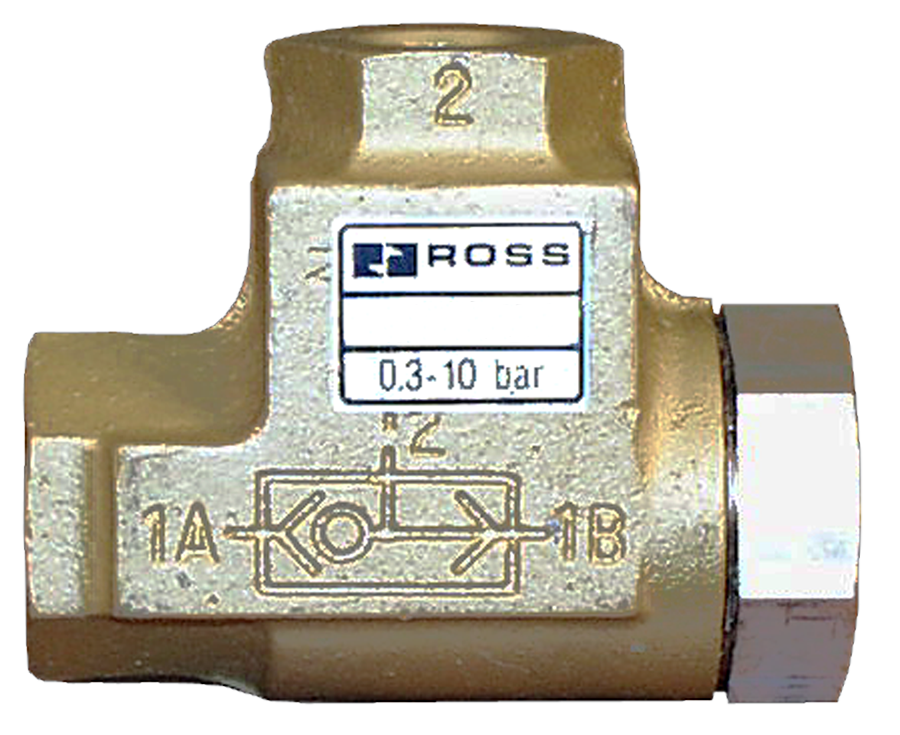
| Operating Pressure | 5 to 150 psig (0.3 to 10 bar) |
| Flow Media | Filtered Air |
| Valve Body Material | Cast Aluminum |
Temperature Ratings
All 19 Series shuttle valve models share the same extended operating temperature range, enabling use across cold storage, outdoor, and general industrial environments.
| Configuration | Ambient Temperature | Media Temperature |
| Standard Shuttle Valves (1968E) | 40 to 175 F (-40 to 80 C) | 40 to 175 F (-40 to 80 C) |
| High-Flow Shuttle Valves (1968D) | 40 to 175 F (-40 to 80 C) | 40 to 175 F (-40 to 80 C) |
Important: For temperatures below 40 F (4 C), compressed air must be free of water vapor to prevent ice formation inside the valve and on the shuttle sealing surfaces.
Certifications & Compliance
| Certification/Standard | Detail |
| Quality Management | ROSS Controls operates under an ISO 9001 certified quality management system, providing manufacturing consistency and component traceability. |
| Thread Standards | NPT threads comply with ANSI/ASME B1.20.1. BSPP (G) threads comply with ISO 228-1. |
| CE Marking | ROSS Controls products are manufactured to comply with applicable EU Machinery Directive requirements where applicable. |
Typical Applications & Industries
Pneumatic Circuit Design and Logic Control
- OR logic gate function in pneumatic control circuits where a single downstream actuator or pilot signal must be triggered by either of two independent upstream control valves. The shuttle valve replaces two check valves and a tee fitting with a single, compact, purpose-designed component.
- Manual-plus-automatic control architectures where a machine function must be operable either by a manually actuated pushbutton valve or by an automatic pilot signal from the PLC or sequencing valve. The shuttle valve connects both control sources to the actuator without cross-connecting the two signal lines.
- Emergency override circuits where a safety or manual intervention signal must be able to activate a function independently of the primary automatic control circuit, with the shuttle valve ensuring that the emergency signal reaches the actuator regardless of the state of the primary control valve.
- Pneumatic programmable control systems using ladder logic pneumatic valve networks, where shuttle valves serve as OR gates in multi-step sequencing programs that control cylinder sequences based on position sensor inputs.
Machine Safety and Redundant Control
- Redundant pilot supply circuits in dual-channel safety valve systems where two independent solenoid pilot valves must both contribute to the pilot supply, and either valve alone must be capable of maintaining the pilot signal. The shuttle valve combines the two pilot supply lines into a single outlet.
- Dual-station control panels where two operator stations on opposite sides of a machine must both be capable of initiating a function, with the shuttle valve connecting both station outputs to the common actuator pilot line.
- Back-pressure-operated dump circuits where either a manually operated valve or an automatic pressure switch signal can trigger a safety exhaust sequence. The shuttle valve ensures that either signal reaches the dump valve pilot without requiring the operator to physically cross to the alternative control station.
- Manual bypass circuits in automated systems where maintenance personnel must be able to actuate a cylinder or valve function without energizing the full automatic control sequence, using a manual pilot valve connected through a shuttle valve to the actuator.
Assembly and Manufacturing Automation
- Assembly fixture clamping circuits where either a foot pedal valve or a remote palm button valve must be capable of initiating the clamp sequence, allowing the operator to select the most ergonomically appropriate activation method for the current task.
- Transfer line part-present circuits where a shuttle valve connects the outputs of two part-sensor valves positioned at different stages of the fixture to a common signal line, triggering the next cycle step when either sensor detects a part.
- Multi-press tandem circuits where two press cylinders with independent pilot supplies must both contribute to a common pilot signal, with the shuttle valve connecting the two pilot outputs and passing whichever signal arrives first to the main valve pilot.
- Conveyor diverter and gate control circuits where either a limit valve triggered by product passage or a timer-based automatic signal must actuate the gate, with the shuttle valve combining both trigger signals to a single gate actuator pilot.
Cold Storage and Outdoor Applications
- Refrigerated dock door actuator control circuits in cold storage facilities operating at -40 F (-40 C), where the standard shuttle valve maintains reliable OR logic function without shuttle sticking or seal hardening in sustained freezer temperatures.
- Outdoor pneumatic control panels in northern climate installations where the extended temperature rating of the 19 Series shuttle valve prevents shuttle seizing or leakage during cold startup and extended winter operation.
- Mining and aggregate processing equipment control circuits in outdoor installations subject to wide temperature swings, where the poppet construction's tolerance to contaminated air and extended temperature capability provide long service intervals.
- Food and beverage processing equipment control circuits in wash-down environments where two independent control stations must operate the same actuator, and the shuttle valve material compatibility with filtered air and aluminum construction meets sanitary installation requirements.
Ordering and Model Number Configuration
The ROSS 19 Series shuttle valve uses a structured model number system. The letter following '1968' identifies the sub-family. The numeric character identifies the port size. The suffix designates the design variant.
|
Model Number Structure: 1968 - E - 2 - 006
1968 Series designation (19 Series)
E Sub-family: E = Standard Shuttle, D = High-Flow Shuttle
2 Port size code: 1 = 1/8", 2 = 1/4", 3 = 3/8"
006 Variant code (design and revision identifier)
Prefix D = BSPP (G) threads | No prefix = NPT threads |
For BSPP (G) thread models, add 'D' as a prefix to any standard NPT model number (e.g., D1968E2006, D1968D3003).
Contact ROSS Controls at 1-888-TEK-ROSS (835-7677) to confirm current model availability, lead times, and dimensional data.
Standard Shuttle Valves (19 Series)
| port_size | model_npt | model_bspp | avg_cv_1_2 | length_in_mm | width_in_mm | height_in_mm | weight_lb_kg |
| 1/8" | 1968E1006 | D1968E1006 | 0.8 | 1.98 in (50 mm) | 0.75 in (19 mm) | 1.25 in (32 mm) | 0.15 (0.07) |
| 1/4" | 1968E2006 | D1968E2006 | 0.8 | 1.98 in (50 mm) | 0.75 in (19 mm) | 1.25 in (32 mm) | 0.15 (0.07) |
High-Flow Shuttle Valves (19 Series)
| port_size | model_npt | model_bspp | avg_cv_1_2 | length_in_mm | width_in_mm | height_in_mm | weight_lb_kg |
| 1/4" | 1968D2003 | D1968D2003 | 2.0 | 2.64 in (67 mm) | 1.25 in (32 mm) | 2.13 in (54 mm) | 0.8 (0.4) |
| 3/8" | 1968D3003 | D1968D3003 | 3.0 | 2.64 in (67 mm) | 1.25 in (32 mm) | 2.13 in (54 mm) | 0.8 (0.4) |
Related Products & Accessories
- Flow Control Valves 19 Series (Series 261) - Low-profile, high-capacity, and right-angle flow control valves for cylinder speed control. Cv to 50, port sizes 1/8 to 2-1/2 in. https://www.rosscontrols.com/en/series/261-flow-controls
- Check Valves 19 Series (Series 262) - Self-actuating poppet check valves for backflow prevention, low cracking pressure, and in-line serviceability. Cv to 50. https://www.rosscontrols.com/en/series/262-check-valves
- Quick Exhaust Valves 18 Series (Series 264) - Poppet-construction quick exhaust valves for rapid cylinder retraction with Cv up to 10 at the cylinder port. https://www.rosscontrols.com/en/series/264-quick-exhaust-valves
- Exhaust Silencers (Series 90) - Aluminum silencers rated to 290 psig for reducing exhaust noise on valve and cylinder exhaust ports. https://www.rosscontrols.com/en/series/90-silencers
- Lockout Valves L-O-X Series - OSHA-compliant lockout/tagout energy isolation valves for safe maintenance of pneumatic machinery. https://www.rosscontrols.com/en/series/1287-lockout-valves-15-series
Frequently Asked Questions (FAQ)
Q: What is the difference between a shuttle valve and a double check valve?
A: The terms shuttle valve and double check valve are used interchangeably for the same valve type: a valve with two inlet ports and one outlet that automatically connects the pressurized inlet to the outlet while blocking the unpressurized inlet. ROSS uses the term shuttle valve in the 19 Series product designation.
Q: How does the shuttle valve prevent cross-flow between the two supply sources?
A: The internal shuttle element, a poppet or ball that spans both inlet seats, seals against one inlet seat when pressure is applied to the opposite inlet. The higher-pressure inlet pushes the shuttle against the opposite seat, forming a positive seal that prevents flow from the pressurized inlet from traveling back to the unpressurized inlet. This creates complete hydraulic isolation between the two supply sources.
Q: What happens when both inlets are pressurized simultaneously?
A: When both inlets are pressurized equally, the shuttle rests in an intermediate position and both inlets may partially communicate with the outlet. In practice, one inlet will usually be at marginally higher pressure and will seat the shuttle against the lower-pressure inlet. For circuits that require guaranteed isolation when both inlets are simultaneously pressurized, consult ROSS Controls for guidance on the appropriate valve selection.
Q: What is the operating pressure range?
A: All 19 Series shuttle valve models operate from 5 to 150 psig (0.3 to 10 bar). This covers both low-pressure pilot signal circuits (typically 60 to 80 psig) and full supply pressure circuit applications.
Q: What temperature range is supported?
A: All 19 Series shuttle valve models support ambient and media temperatures from -40 to 175 F (-40 to 80 C), covering cold storage, outdoor, and general industrial environments.
Q: What is the difference between the standard and high-flow shuttle valve models?
A: Standard models (1968E series) cover 1/8 and 1/4 in. ports with Cv 0.8 for pilot signal circuits and small actuators. High-flow models (1968D series) cover 1/4 and 3/8 in. ports with Cv 2.0 to 3.0 for larger actuators and main supply circuits requiring higher flow capacity. The 1/4 in. port size is available in both families, so Cv requirement determines which sub-family to specify.
Q: How do I order BSPP (G thread) models?
A: Add a 'D' prefix to any standard NPT model number. For example, the 3/8 in. NPT high-flow shuttle valve is 1968D3003; the BSPP equivalent is D1968D3003. This applies to both standard and high-flow shuttle valve families.
Q: Can the shuttle valve be used in a pressure sequence circuit?
A: Yes. In a pressure sequence circuit, the shuttle valve can connect the outputs of two sequence valves set at different pressures, with the lower-pressure valve output triggering the downstream actuator first and the higher-pressure valve output shifting the shuttle to take over the signal after the first pressure setpoint is reached.
Q: Is the shuttle valve directional? Does it need to be installed with a specific inlet orientation?
A: The two inlet ports (1A and 1B) are functionally identical. Either inlet can receive the first or second pressure signal. The outlet port (port 2) is the connection to the downstream actuator or pilot. In the inline body design, the outlet port is physically distinct from the inlet ports, but either inlet can be connected to either supply source.
Q: What filtration is required?
A: A 5-micron air filter is recommended in the supply lines feeding the shuttle valve inlets. While the poppet design provides contamination tolerance, particulate accumulation on the shuttle seating surfaces over time can cause leakage in the closed position and delayed shuttle response.
Q: Can the shuttle valve be used as a check valve?
A: A shuttle valve blocks reverse flow from the outlet back to either inlet, which is similar to check valve behavior. However, it is not rated or designed as a dedicated check valve and should not be substituted for a check valve where positive backflow shutoff at low differential pressure is the primary circuit requirement. Use the 19 Series check valve (Series 262) for backflow prevention applications.
Q: What is the maximum Cv available in the 19 Series shuttle valve line?
A: The maximum Cv is 3.0, available in the high-flow 3/8 in. port model (1968D3003). For circuits requiring higher flow through an OR logic valve, contact ROSS Controls for guidance on alternative circuit architectures or higher-flow valve options.
Installation & Maintenance Guidelines
- Before installing or servicing any valve, shut down the complete pneumatic system, exhaust all pressure, and lock out all energy sources per OSHA 1910.147 and EN 1037.
- Identify the two inlet ports (1A and 1B) and the single outlet port (2) on the shuttle valve body before installation. Connecting the outlet to a supply source and an inlet to the actuator will result in uncontrolled actuator pressurization.
- Install a 5-micron air filter in the supply lines feeding both inlet ports. Contamination on shuttle seating surfaces is the primary cause of shuttle valve leakage and delayed response in service.
- Apply thread sealant to male pipe threads only. Use PTFE tape or pipe thread compound compatible with compressed air service. Keep sealant away from the thread start to prevent contamination from entering the valve body.
- Ensure that the pipe connections to both inlets are fully tightened to standard NPT or BSPP torque specifications for the port size. Under-tightened connections in pilot signal circuits can introduce air leaks that produce false pilot signals.
- For installations in cold storage or freezer environments below 40 F (4 C), verify that compressed air is dried to a dew point below the minimum operating temperature before the system is started. Ice formation on the shuttle can prevent it from shifting between inlet positions.
- After installation, test the shuttle function by pressurizing inlet 1A while 1B is vented and verifying that flow exits port 2. Then pressurize 1B and verify that the shuttle shifts and flow again exits port 2, with port 1A now blocked. Both inlet positions must be tested.
- Do not exceed the maximum operating pressure of 150 psig (10.3 bar) on either inlet. Overpressure can deform the shuttle element or sealing surfaces, causing permanent leakage in the blocked inlet position.
- When replacing an existing shuttle valve, verify that the replacement model matches the original port size and sub-family (standard or high-flow). Substituting a standard model for a high-flow model in a high-flow circuit will restrict actuator performance.
- In circuits where the two supply signals are at significantly different pressures during normal operation, verify that the higher-pressure signal does not cause excessive leakage past the lower-pressure inlet seat at the maximum operating differential.
- For inline piping installations with large-bore connections, support the piping adjacent to both inlet ports to prevent cantilever loads from being transmitted to the valve body through the threaded connections.
- After completing installation and testing, document the supply source connections to each inlet port in the machine circuit diagram. This documentation is critical for troubleshooting shuttle valve behavior during maintenance and fault diagnosis.
Warranty & Global Support
ROSS Controls provides a one-year warranty on all shuttle valve products, covering defects in material and workmanship from date of purchase.
Global technical support is available through ROSS offices in the USA (headquarters in Ferndale, Michigan), Canada, Brazil, Germany, France, United Kingdom, India, China, and Japan.
Contact ROSS Controls USA Customer Service at 1-800-GET-ROSS (438-7677) or Technical Service at 1-888-TEK-ROSS (835-7677) for circuit design guidance, product selection, and field troubleshooting.
For complete dimensional drawings, Cv data, and ordering information, visit the ROSS Controls 19 Series product page at rosscontrols.com or download the catalog from the ROSS documents page.
Download Catalog: https://www.rosscontrols.com/en/documents/387
Download Documents
Shuttle Valves
