Check Valves 19 Series

- Self-cleaning poppet design tolerates dirty air
- Low cracking pressure
- Serviceable in-line
- Quiet operation due to soft-seal design
Check Valves 19 Series Product Overview
ROSS check valves function is to open with fluid movement and pressure, and close to prevent backflow of the pressure to upstream equipment. ROSS check valves are self-actuating and designed to provide free air flow in one direction, and to be closed to flow in the opposite direction.
Please refer to the side and below for links to easily navigate and download ROSS Controls Check Valves 19 Series catalogs, installation instructions, and technical data. Additionally, you have the option to filter through all available options to Check Valves 19 Series variant that meets your requirements.
loading...
loading...
Product Overview
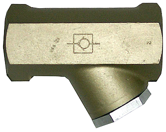
The ROSS Controls 19 Series Check Valves are self-actuating pneumatic valves designed to allow unrestricted free air flow in one direction while completely blocking reverse flow to upstream equipment. The 19 Series check valve line covers three capacity ranges within a single product family: low-profile models for small-port and space-critical installations, mid-range models for medium-flow circuits, and high-capacity models for large-bore cylinder and high-flow pneumatic systems.
Check valves open in response to downstream pressure differential and flow demand, and close automatically when flow reverses or pressure drops below the cracking threshold. In pneumatic circuits, check valves serve critical functions including pilot supply isolation, cylinder cushion control, accumulator circuit protection, and enabling parallel flow paths with independent directional control. They are also used in tandem with flow control valves to create separate meter-in and meter-out flow paths for asymmetric cylinder speed control.
All 19 Series check valves use poppet construction, which provides three distinct performance advantages over ball-type and disc-type alternatives: low cracking pressure that allows the valve to open at minimal differential pressure, a soft-seal poppet design that provides quiet operation without the metallic seat impacts common in hard-seat valves, and self-cleaning action from high-velocity air flow across the poppet face that prevents particulate accumulation on the sealing surface.
The 19 Series check valve body is designed for in-line serviceability. The poppet, spring, and seals are accessible without removing the valve from the pipeline, reducing maintenance downtime and simplifying field inspection. Available in NPT and BSPP (G) thread formats across port sizes from 1/8 in. through 2 in., the 19 Series check valves serve the complete range of industrial pneumatic circuit requirements.
Key Engineering Features
- Self-Cleaning Poppet Design - High-velocity air flow across the poppet seat continuously cleans contamination from sealing surfaces, providing strong tolerance to dirty compressed air without compromising shutoff performance.
- Low Cracking Pressure - Poppet geometry and spring selection provide low cracking pressure, allowing the valve to open with minimal upstream-to-downstream pressure differential and avoiding unnecessary pressure drop in circuits where every psi matters.
- Soft-Seal Poppet for Quiet Operation - The elastomeric poppet seal contacts the seat without metallic impact, providing quiet operation during cycling and reducing noise levels compared to metal-seat check valves in high-cycle applications.
- Serviceable In-Line - Poppet, spring, and seal components are accessible through the valve body without removing the valve from the pipeline, enabling field maintenance and inspection without system disassembly.
- Three Capacity Ranges in One Product Family - Low-profile, mid-range, and high-capacity sub-families within the 19 Series cover Cv values from 0.5 to 50 in a consistent product architecture, simplifying valve selection and spare parts management.
- NPT and BSPP Thread Availability - All models are available with NPT threads for North American applications and with BSPP (G) threads for international equipment, with the 'D' prefix designating BSPP models in the ordering system.
- Extended Temperature Range - All 19 Series check valve models support ambient and media temperatures from -40 to 175 F (-40 to 80 C), enabling use in cold storage, outdoor, and moderately elevated-temperature environments.
- Cast Aluminum Body Construction - Cast aluminum valve bodies provide the combination of low weight, corrosion resistance, and structural integrity required for long-term inline mounting in industrial pneumatic circuits.
- Poppet Construction Tolerant of Contaminated Air - Unlike spool or ball check designs that can stick or fail to seal when contaminated, the poppet mechanism remains functional in the presence of particulates and light oil mist common in industrial compressed air systems.
- Pilot Supply Minimum Equal to or Greater Than Inlet - The valve's pilot supply requirement equals or exceeds inlet pressure, ensuring positive shutoff across the full operating pressure range without requiring separate pilot supply circuits.
Technical Specifications
General Specifications
| Parameter | Specification |
| Valve Type | Check Valve |
| Valve Series | 19 Series |
| Construction | Poppet |
| Function | 2/2 |
| Actuation | Pneumatic (self-actuating) |
| Mounting | Inline |
| Thread Types | NPT (standard); G/BSPP (add 'D' prefix to model number) |
| Port Sizes - Low-Profile | 1/8", 1/4" |
| Port Sizes - Mid-Range | 1/4", 3/8", 1/2" |
| Port Sizes - High-Capacity | 1/2", 3/4", 1", 1-1/4", 2" |
| Max Cv - Low-Profile | 0.5 |
| Max Cv - Mid-Range | 3.9 |
| Max Cv - High-Capacity | 50 |
| Operating Pressure | 5 to 150 psig (0.3 to 10 bar) |
| Pilot Supply Minimum | Equal to or greater than inlet pressure |
| Flow Media | Filtered Air |
| Valve Body Material | Cast Aluminum |
Temperature Ratings
All 19 Series check valve models share the same extended temperature envelope, covering cold storage to moderately hot industrial environments.
| Configuration | Ambient Temperature | Media Temperature |
| All 19 Series Check Valve Models | 40 to 175 F (-40 to 80 C) | 40 to 175 F (-40 to 80 C) |
Important: For media temperatures below 40 F (4 C), compressed air must be free of water vapor to prevent ice formation inside the valve and on the poppet sealing surfaces.
Certifications & Compliance
| Certification/Standard | Detail |
| Quality Management | ROSS Controls operates under an ISO 9001 certified quality management system, providing manufacturing consistency and component traceability. |
| Thread Standards | NPT threads comply with ANSI/ASME B1.20.1. BSPP (G) threads comply with ISO 228-1. |
| CE Marking | ROSS Controls products are manufactured to comply with applicable EU Machinery Directive requirements where applicable. |
Typical Applications & Industries
Pneumatic Circuit Design and Control
- Pilot supply isolation in directional control valve circuits, where a check valve prevents pilot air from back-feeding into the supply line when the main valve shifts, ensuring consistent pilot pressure and reliable valve response.
- Accumulator circuit protection in pneumatic storage systems, where the check valve allows the accumulator to charge from the supply and prevents stored energy from discharging back through the compressor or regulator when supply pressure drops.
- Parallel flow path circuits that combine check valves with flow control valves to achieve independent meter-in and meter-out control, enabling different extension and retraction speeds without complex directional valve configurations.
- Emergency stop and safety exhaust circuits where check valves in the pilot supply line ensure that safety valves de-energize correctly without back-pressure from downstream volumes interfering with the exhaust path.
Cylinder and Actuator Control
- Cylinder cushion circuit check valves that allow free flow into the cushion cavity during extension while the flow control restricts exhaust during retraction, decelerating the piston smoothly near end of stroke.
- Tandem cylinder synchronization circuits where check valves prevent cross-flow between parallel cylinder branches, maintaining independent pressure balance and synchronized motion under varying load conditions.
- Vertical cylinder load-holding applications where a check valve in the cap-end supply line prevents gravity-induced cylinder drift when the directional control valve is in the center position, supplementing spool center-closed function.
- Regenerative cylinder circuits where a check valve in the rod-end-to-supply connection enables the rod-end exhaust flow to supplement cap-end supply during extension, increasing extension speed without additional compressor capacity.
General Industrial and Process
- Air reservoir and receiver circuit protection, where check valves in the supply connection prevent backflow from the receiver to the compressor outlet during compressor unloaded cycles, protecting compressor valves and reducing energy loss.
- Pressure sequence and interlock circuits where check valves establish pressure priority between circuit branches, ensuring that upstream functions complete before downstream actuators receive supply pressure.
- Pneumatic logic circuits in legacy programmable pneumatic systems where check valves function as one-way OR gates, allowing signal flow from one of multiple sources without cross-contamination between signal paths.
- Cold storage and refrigeration facility pneumatic controls using the -40 F (-40 C) rated 19 Series models, maintaining backflow prevention and low cracking pressure through sustained freezer environment operation.
Automotive and Assembly Manufacturing
- Welding gun retract circuit check valves that prevent electrode force loss during the welding cycle by isolating the cap-end supply from the rod-end retract circuit, maintaining consistent electrode force regardless of directional valve center condition.
- Assembly fixture clamp circuit check valves that hold clamping force during machine cycle interruptions or supply pressure fluctuations without requiring continuous solenoid energization.
- Transfer line index and locate actuator check valves that maintain part position between machine cycles by preventing cylinder retraction due to back-pressure or load-induced pressure reversal.
- Paint shop conveyor actuator pilot supply check valves that isolate pilot circuits from supply pressure variations caused by demand fluctuations across the paint line, ensuring consistent actuator response throughout the shift.
Ordering and Model Number Configuration
The ROSS 19 Series check valve uses a structured model number system. The letter following '1968' identifies the sub-family capacity range. Port size is encoded in the numeric characters. The suffix digits identify the valve variant within the family.
|
Model Number Structure: 1968 - A - 5 - 107
1968 Series designation (19 Series check valves)
A Sub-family: D = Low-Profile/Mid-Range, A = High-Capacity
5 Port size code: 1 = 1/8", 2 = 1/4", 3 = 3/8", 4 = 1/2", 5 = 3/4", 6 = 1", 7 = 1-1/4", 9 = 2"
107 Variant code (identifies body size, port size offset, and design revision)
Prefix D = BSPP (G) threads | No prefix = NPT threads |
For BSPP (G) thread models, add 'D' as a prefix to any standard NPT model number (e.g., D1968D1005, D1968A5107).
High-capacity models with a body size larger than the port size use a '1' in the last three digits to indicate reduced-port configuration (e.g., 1968A6117 = 1 in. port in 3/4 in. body).
Contact ROSS Controls at 1-888-TEK-ROSS (835-7677) for complete model number breakdowns and dimensional data for all check valve configurations.
Low-Profile Check Valves (19 Series)
| port_size | model_npt | avg_cv | length_in_mm | width_in_mm | height_in_mm | weight_lb_kg |
| 1/8" | 1968D1005 | 0.5 | 2.65 in (67 mm) | 1.15 in (29 mm) | 1.0 in (25 mm) | 0.5 (0.2) |
| 1/4" | 1968D2001 | 0.5 |
Mid-Range Check Valves (19 Series)
| port_size | model_npt | avg_cv |
| 1/4" | ||
| 3/8" | 1968D3001 | 3.7 |
| 1/2" | 1968D4001 | 3.9 |
High-Capacity Check Valves (19 Series) - Body size is the internal body bore; port size is the pipe thread size. The 3/4 in. body accepts 1/2 in., 3/4 in., and 1 in. port threads.
| port_size | body_size | model_npt | avg_cv | length_in_mm | width_in_mm | height_in_mm | weight_lb_kg |
| 1/2" | 3/4 | 1968A4107 | 5.2 | 4.52 in (114.8 mm) | 1.76 in (44.7 mm) | 3.37 in (85.6 mm) | 0.9 (0.4) |
| 3/4" | 3/4 | 1968A5107 | 8.6 | 4.52 in (114.8 mm) | 1.76 in (44.7 mm) | 3.37 in (85.6 mm) | 0.9 (0.4) |
| 1" | 3/4 | 1968A6117 | 8.3 | 4.52 in (114.8 mm) | 1.76 in (44.7 mm) | 3.37 in (85.6 mm) | 0.9 (0.4) |
| 1-1/4" | 1-1/4 | 1968A7107 | 22 | 5.35 in (135.9 mm) | 2.36 in (60.0 mm) | 4.27 in (108.5 mm) | 2.0 (0.9) |
| 2" | 2 | 1968A9107 | 50 | 7.47 in (189.7 mm) | 3.51 in (89.2 mm) | 6.65 in (168.9 mm) | 4.7 (2.1) |
Related Products & Accessories
- Flow Control Valves 19 Series (Series 261) - Low-profile, high-capacity, and right-angle flow control valves for pneumatic cylinder speed control. Cv to 50, port sizes 1/8 to 2-1/2 in. https://www.rosscontrols.com/en/series/261-flow-controls
- Shuttle Valves 19 Series (Series 263) - Dual-inlet, single-outlet shuttle valves for OR-logic circuits. Standard and high-flow models available. https://www.rosscontrols.com/en/series/263-shuttle-valves
- Quick Exhaust Valves 18 Series (Series 264) - Poppet-construction quick exhaust valves for rapid cylinder retraction by providing short-path exhaust bypass at the cylinder port. https://www.rosscontrols.com/en/series/264-quick-exhaust-valves
- Exhaust Silencers (Series 90) - Aluminum silencers rated to 290 psig for reducing exhaust noise at valve and cylinder exhaust ports. https://www.rosscontrols.com/en/series/90-silencers
- Lockout Valves L-O-X Series - OSHA-compliant lockout/tagout energy isolation valves for safe maintenance of pneumatic machinery. https://www.rosscontrols.com/en/series/1287-lockout-valves-15-series
Frequently Asked Questions (FAQ)
Q: What is the function of a check valve in a pneumatic circuit?
A: A check valve allows free air flow in one direction (from port 1 inlet to port 2 outlet) and blocks flow in the reverse direction. When downstream pressure drops or upstream flow reverses, the poppet closes automatically under spring and differential pressure force, preventing backflow to upstream equipment or supply lines.
Q: What is cracking pressure and why does it matter?
A: Cracking pressure is the minimum upstream-to-downstream pressure differential required to open the check valve and initiate flow. Low cracking pressure means the valve opens with minimal pressure drop, preserving available system pressure for actuator work. High cracking pressure wastes supply pressure and can prevent circuits from activating at low supply pressures.
Q: What makes the 19 Series check valve self-cleaning?
A: The poppet design directs air flow at high velocity across the poppet seat when open. This jet action dislodges particulates from the sealing surfaces before the poppet closes, preventing contamination buildup that could compromise the seal. This is fundamentally different from ball-seat designs, where particulates can lodge between the ball and seat and prevent full closure.
Q: Can the 19 Series check valve be serviced without removing it from the pipeline?
A: Yes. The poppet, spring, and seat seals are accessible through the valve body end cap or body assembly without unthreading the valve from the pipe connections. This in-line serviceability reduces maintenance time and avoids the need to break pipe joints and replace thread sealant during routine inspections.
Q: What is the operating pressure range?
A: All 19 Series check valve models operate from 5 to 150 psig (0.3 to 10 bar). The pilot supply minimum is equal to or greater than inlet pressure, meaning the valve will hold positive shutoff at any inlet pressure within the rated range.
Q: What temperature range is supported?
A: All 19 Series check valve models support ambient and media temperatures from -40 to 175 F (-40 to 80 C). This covers cold storage and freezer applications, standard factory environments, and moderately elevated-temperature processes.
Q: What is the difference between the low-profile, mid-range, and high-capacity sub-families?
A: Low-profile models (Cv 0.5) are compact aluminum valves for 1/8 and 1/4 in. ports in space-constrained locations. Mid-range models (Cv up to 3.9) cover 1/4 through 1/2 in. ports for medium-flow circuits. High-capacity models (Cv up to 50) cover 1/2 in. through 2 in. ports for large-bore cylinder and high-flow system applications.
Q: How do I specify BSPP (G thread) models?
A: Add a 'D' prefix to any standard NPT model number. The BSPP equivalent of model 1968A5107 (3/4 in. NPT high-capacity) is D1968A5107. This convention applies across all 19 Series check valve sub-families.
Q: Can check valves be used for load holding on vertical cylinders?
A: A check valve in the cap-end supply line will prevent gravity-induced downward drift by blocking back-flow from the cylinder cap end to the supply line. However, a check valve alone is not a load-holding safety device. For positively locked vertical cylinder applications in safety-critical situations, use a pilot-operated check valve or a positively locked mechanical brake, not a spring-return check valve.
Q: What filtration is recommended upstream of a check valve?
A: A 5-micron air filter is recommended. While the poppet design provides self-cleaning tolerance to contamination, excessive particulate loading will eventually degrade the elastomeric poppet seal and compromise cracking pressure consistency. Filtration is particularly important in systems with check valves in pilot supply lines, where poppet contamination can cause delayed valve opening.
Q: What is the maximum Cv available in the 19 Series check valve line?
A: The maximum Cv is 50, available in the high-capacity 2 in. port model (1968A9107). This Cv rating supports large-bore cylinders and high-flow circuit requirements without significant pressure drop across the check valve in the free-flow direction.
Q: Are check valves and flow control valves used together in the same circuit?
A: Yes. A common circuit configuration places a flow control valve in parallel with a check valve to achieve independent speed control in each direction. The check valve provides free flow in the direction opposite to the flow control restriction, while the flow control meters the exhaust. This combination enables asymmetric extension and retraction speeds with a single set of components per cylinder port.
Installation & Maintenance Guidelines
- Before installing or servicing any valve, shut down the complete pneumatic system, exhaust all pressure, and lock out all energy sources per OSHA 1910.147 and EN 1037.
- Verify port 1 (inlet) is connected to the supply or upstream side of the circuit and port 2 (outlet) is connected downstream. Installing the valve backward will block supply flow and pass exhaust in the reverse direction, causing system malfunction.
- Install a 5-micron air filter upstream of the check valve in the supply line. Particulate contamination is the primary cause of premature poppet seal wear and seat leakage in check valve applications.
- Apply thread sealant to male pipe threads only. Use PTFE tape or anaerobic pipe thread compound compatible with compressed air service. Keep sealant away from the first thread to prevent debris from entering the valve body on initial pressurization.
- For high-capacity models installed in piping systems, support the piping on both sides of the valve to prevent mechanical stress from being transmitted through the valve body threads. Unsupported piping imposes bending loads that can crack the cast aluminum body over time.
- After installation and before initial pressurization, verify that the valve body end cap or access plug is correctly tightened to the specification in the ROSS installation instructions for that model.
- For cold storage and freezer installations below 40 F (4 C), verify that compressed air is dried to a dew point at or below the minimum operating temperature before the system is started. Ice formation on the poppet or seat will cause the valve to stick open or fail to seal.
- Do not use the check valve as a pressure relief device or allow operating pressure to exceed 150 psig (10.3 bar). Overpressure can permanently deform the elastomeric poppet seal and spring, causing permanent leakage in the closed position.
- When installing low-profile models (1968D series) in small-port pilot circuits, ensure that supply tubing ID is at least as large as the valve port to prevent the tubing from becoming the flow restriction rather than the check valve.
- After installation, perform a functional test by pressurizing the supply side to operating pressure and verifying zero flow or leakage in the reverse direction. Then verify free flow in the forward direction at the minimum operating pressure of the circuit.
- If the check valve is being used in a load-holding application on a vertical cylinder, verify the full holding capacity by applying a load and observing for cylinder drift over a minimum of 60 seconds at the maximum expected load. Document test results for maintenance records.
- For in-line service, isolate the valve from the circuit, relieve all pressure, and access the poppet assembly through the end cap. Inspect the poppet seal, spring, and seat for wear or contamination. Replace the complete poppet assembly with ROSS service kit components rather than individual parts.
Warranty & Global Support
ROSS Controls provides a one-year warranty on all check valve products, covering defects in material and workmanship from date of purchase.
Global technical support is available through ROSS offices in the USA (headquarters in Ferndale, Michigan), Canada, Brazil, Germany, France, United Kingdom, India, China, and Japan.
Contact ROSS Controls USA Customer Service at 1-800-GET-ROSS (438-7677) or Technical Service at 1-888-TEK-ROSS (835-7677) for product selection, circuit application assistance, and field troubleshooting.
For complete dimensional drawings, Cv data, and ordering information, visit the ROSS Controls 19 Series product page at rosscontrols.com or download the Flow Control Valves catalog from the ROSS documents page.
Download Catalog: https://www.rosscontrols.com/en/documents/387
Download Documents
Check Valves