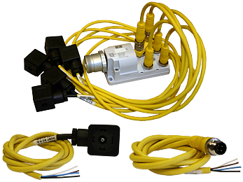
Preassembled Wiring Kits For DM, M35, SV27 & RSe Series

- Available for connecting solenoids, sensing switches, and status indicators
- M12 & DIN connector options
- 24V DC & 120V AC lighted versions available
loading...
loading...
Product Overview
The ROSS Controls preassembled wiring kits are complete cable and connector assemblies engineered specifically for ROSS safety valve stations including DM1 Series, DM2 Series, M35 Series, SV27 Series, and RSe Series double valves. Each kit includes all cables required to connect valve solenoids, sensing switches, and status indicators to the control system junction box or I/O module in a single assembly.
These wiring kits eliminate field termination errors and reduce installation time for complex safety valve stations that require simultaneous connections to two or more solenoids, sensing switches, and pressure-based status indicators. The DM Series and SV27 Series require coordinated wiring of multiple functional elements; the series kits supply correctly matched cable lengths, connector types, and polarities for each connection point.
The product family covers four distinct wiring scenarios: (1) solenoid wiring kits using EN 175301-803 Form A or M12 connections for DM1 Series E and C and DM2 Series E valves, (2) solenoid and sensing switch wiring kits for SV27 Series sensing valves, (3) J-Box splitter assemblies for DM Series outlet port pressure monitoring, and (4) 10-pin mini control system cables for connection between junction boxes and PLCs or safety controllers.
The Series also includes the 2251H77 outlet port pressure monitoring wiring kit that connects a single cable from the junction box to a sensing switch for downstream pressure verification, addressing the specific status indication wiring requirement of DM2 Series C valve configurations using the J-Box pressure monitoring option.
Key Engineering Features
- Complete Multi-Cable Valve Station Assemblies - Each kit includes all cables needed for a complete valve station connection, eliminating the need to source and assemble individual connector components for complex multi-element valve configurations.
- DM1/DM2, M35, SV27, and RSe Compatibility - Kits are engineered and validated for specific ROSS safety valve series, ensuring correct connector types, cable lengths, and pin assignments for each solenoid, sensing switch, and status indicator connection.
- M12 and DIN EN 175301-803 Connector Options - Solenoid connection kits available with either EN 175301-803 Form A DIN connectors or M12 connectors, matching the solenoid connection type ordered with the valve.
- 5 Meter and 10 Meter Length Options - Standard kits available in 5 meter (16.4 ft) and 10 meter (32.8 ft) cable lengths to accommodate different valve-to-control panel distances without custom cable fabrication.
- Lighted Solenoid Connector Options - DM2 Series C solenoid kits available with lighted EN connectors for 24 VDC and 120 VAC coil voltages, providing per-solenoid visual indication.
- J-Box Splitter Assemblies for Pressure Monitoring - Dedicated J-Box wiring kits (2249H77, 2250H77) connect the control system to the valve junction box with combined solenoid and sensing connections in a single 1-meter assembly.
- 10-Pin Mini Cable for System Integration - 10-pin mini cables (2253H77 through 2256H77) in 12, 20, 30, and 50 foot lengths connect junction boxes to PLC I/O modules and safety controllers.
- Factory Cord Grips Included - Solenoid connector kits for DM1/DM2 E and C Series include cord grips at each solenoid connector, ensuring proper sealing and strain relief for all connections.
- Outlet Port Pressure Monitoring Kit - The 2251H77 1-meter outlet port pressure monitoring kit provides a single dedicated cable from the J-Box to the sensing switch for downstream pressure status.
- SV27 Solenoid and Sensing Switch Combined Kits - SV27 Series kits combine solenoid and sensing switch cables in one assembly, ensuring cable lengths are matched between the two functional connections.
Technical Specifications
General Specifications
| Parameter | Specification |
| Compatible Valve Series | DM1 Series E and C, DM2 Series E and C, M35 Series, SV27 Series, RSe Series |
| Solenoid Connection Types | DIN EN 175301-803 Form A; M12 (5-pin) |
| Wire Gauge | 18 AWG |
| Standard Cable Lengths | 1 m, 4 m, 5 m, 10 m, 12 ft, 20 ft, 30 ft, 50 ft (varies by kit) |
| LED Indicator Voltages | 24 VDC (W suffix), 120 VAC (Z suffix) |
| 10-Pin Mini Cable | 18-gauge wire, 4 cable versions per set where applicable |
| J-Box Splitter | Connects control system to valve J-Box for combined solenoid and status indicator wiring |
Certifications & Compliance
Typical Applications & Industries
Press Room Safety Systems
- Hydraulic and mechanical press installations using DM2 Series C double valves for press clutch/brake control. The 2283H77 or 2284H77 solenoid wiring kits provide matched-length cables to both solenoids, ensuring simultaneously the same cable routing resistance and therefore equal electrical timing.
- Stamping press lines requiring Category 4 PLe safety performance where wiring integrity is part of the safety validation. Factory-preassembled kits with tested connections reduce the risk of wiring errors that could compromise safety function response times.
- Transfer press installations with multiple valve stations on a common tooling bed where the 10-meter kit options (2284H77) reach the control panel from valve positions throughout the press structure without field splicing.
Robotic Welding and Automation
- Robotic cell enabling devices using DM2 Series C safe exhaust double valves. The preassembled wiring kits comply with the cable documentation requirements of machine safety validations under ISO 13849 and IEC 62061.
- Safety zones controlled by SV27 Series sensing valves where the 2239H77 or 2240H77 combined solenoid and sensing switch kits provide both actuation and feedback wiring in a single installation step.
- Fixture loading stations where valve J-Box wiring kits (2249H77, 2250H77) consolidate wiring from the fixture pneumatic valve to the safety PLC I/O using standardized M12 multi-pin connectors.
Energy Isolation and Lockout/Tagout
- Machine lockout systems using ROSS L-O-X valves with pilot solenoids where the SV27 sensing valve kits provide both solenoid actuation and downstream pressure sensing cables needed for monitored energy isolation.
- Pneumatic press brake safety systems requiring simultaneous actuation and monitoring of two solenoid channels with individual status feedback to the safety controller.
- Conveyor and material handling lockout points where preassembled M12 sensor connector kits (2644B77 or 2645B77) provide standardized connections for solid-state sensors monitoring valve position.
PLC and Safety Controller Integration
- Siemens, Allen-Bradley, and other safety PLC installations where the 10-pin mini cables (2253H77 through 2256H77) provide standardized connections between ROSS valve J-Boxes and safety PLC I/O modules.
- Safety relay-controlled press installations where the consistent cable construction and tested connector assemblies support the wiring documentation required for CE marking and OSHA compliance.
- Distributed control systems where M12 sensor connector kits create standardized interface points between ROSS valve status indicators and field bus devices or remote I/O modules.
Original Equipment Manufacturers
- Machine builders specifying ROSS DM2 or SV27 Series safety valves as catalog components, including the matching Series wiring kits in the machine bill of materials for consistent electrical installation across production runs.
- Export machine builders requiring complete wiring assemblies that meet both North American (NEC) and European (EN) wiring standards, supported by the documented DIN EN 175301-803 connector compliance of the series.
- High-volume OEM installations where preassembled kits reduce assembly labor time compared to field-wired individual connector assemblies, improving consistency and reducing defect rates in production.
Ordering and Model Number Configuration
Select the wiring kit based on the specific valve series (DM1, DM2, SV27, CM) and the solenoid connection type ordered with the valve (DIN EN 175301-803 Form A or M12).
For DM2 Series C with lighted solenoid connectors, specify the lighted kit number: 2532H77-W (24 VDC) or 2532H77-Z (120 VAC) for 5-meter length; 2533H77-W or 2533H77-Z for 10-meter.
J-Box wiring kits 2249H77 (M12/DIN) and 2250H77 (M12/M12) are for 24 VDC systems only.
10-pin mini cables are ordered by length: 2253H77 (12 ft), 2254H77 (20 ft), 2255H77 (30 ft), 2256H77 (50 ft).
M12 sensor connector kits specify connection style (one-end or both-ends) and cable quantity. Double-check the number of cables per kit against the number of sensors on the valve station.
For SV27 Series, determine whether solenoid-only, sensing-only, or combined solenoid-and-sensing kit is required based on the valve station wiring configuration.
All wiring kits are designed for indoor and IP65-compatible applications. For outdoor or high-temperature environments, contact ROSS for material compatibility verification.
Related Products & Accessories
- 91 Series Electrical Connectors - Individual DIN EN 175301-803 Form A, B, and C connectors for ROSS solenoid valves, used where preassembled kits are not required. https://www.rosscontrols.com/en/series/91-electrical-connectors
- 92 Series Prewired Electrical Connectors - Factory prewired single-cable DIN connector assemblies for individual solenoid valve connections. https://www.rosscontrols.com/en/series/92-prewired-electrical-connectors
- 2854 Series Solid State Pressure Sensors - M12-connected solid-state pressure sensors for valve status indication compatible with Series M12 connector kits. https://www.rosscontrols.com/en/series/2854-solid-state-pressure-sensor
- 95 Series Mechanical Pressure Switches - DIN EN 175301-803 Form A connected pressure switches for energy release verification on L-O-X valves, wired using 91/92 Series connectors. https://www.rosscontrols.com/en/series/95-mechanical-pressure-switches
- DM2 Series Double Valves - Primary safety exhaust double valve series for which Series wiring kits 2283H77 through 2289H77 are designed. https://www.rosscontrols.com/en/series
Frequently Asked Questions (FAQ)
Q: Which wiring kit do I need for a DM2 Series C valve with DIN EN 175301-803 Form A solenoids?
A: Use the 2283H77 (5-meter) or 2284H77 (10-meter) solenoid wiring kit. These provide two EN 175301-803 Form A solenoid cables with cord grips. If lighted connectors are required, order 2532H77-W (24 VDC) or 2532H77-Z (120 VAC) for the 5-meter lighted version, or 2533H77-W / 2533H77-Z for 10-meter lighted.
Q: Do I need separate wiring kits for solenoids and status indicators on DM1 Series valves?
A: Yes. DM1 Series E and C solenoid wiring kits (2243H77 through 2246H77) cover the solenoid connections. The status indicator connections require separate status indicator kits 2247H77 (5-meter) or 2248H77 (10-meter). Order both kits for a complete valve station installation.
Q: What is the purpose of the 10-pin mini cables?
A: The 10-pin mini cables (2253H77 through 2256H77) connect the valve junction box to the safety controller or PLC I/O module. They carry combined signals for both solenoids and status indicators in a single multi-conductor cable, reducing cable tray congestion compared to running individual cables from valve to panel.
Q: Are the J-Box wiring kits only for 24 VDC systems?
A: Yes. The 2249H77 and 2250H77 J-Box wiring kits are designed for 24 VDC systems only. For AC voltage solenoid valve stations, individual wiring kits for solenoids and status indicators should be used without the J-Box approach.
Q: What is the cable length between the valve and control panel that these kits support?
A: Standard kits cover 5-meter (16.4 ft) and 10-meter (32.8 ft) distances from valve to control connection. For the SV27 Series, a 4-meter (13.1 ft) option is also available. For longer distances, use the appropriate kit combined with a field-installed terminal block at the maximum kit cable reach.
Q: Can I use a DM2 Series C wiring kit (2283H77) for a DM1 Series E valve?
A: The DM1 Series E uses kits 2243H77 through 2246H77 while DM2 Series C uses 2283H77 through 2289H77. Connector types and cable counts may differ between series. Always select the kit designated for the specific valve series being wired.
Q: What is the M12 Outlet Port Pressure Monitoring kit (2251H77) used for?
A: The 2251H77 provides a 1-meter cable from the valve junction box to the sensing switch for outlet port pressure monitoring. This is specifically for DM2 Series C configurations using the J-Box pressure monitoring option, where a separate short cable connects the J-Box to the downstream pressure sensing switch.
Q: How many cables are included in the SV27 combined solenoid and sensing kit?
A: The 2239H77 (4-meter) and 2240H77 (10-meter) combined kits each include 2 cables: one for the solenoid and one for the sensing switch. The sensing-switch-only kits (2241H77, 2242H77) each include 1 cable for the sensing switch only.
Q: Are M12 sensor connector kits (2644B77, etc.) the same as solenoid wiring kits?
A: No. The M12 sensor connector kits are for solid-state sensor and status indicator connections, not solenoid actuation wiring. They use M12 5-pin A-coded connectors on one or both ends with flying leads on the other end. Solenoid wiring requires separate kits with EN 175301-803 Form A or M12 solenoid connectors.
Q: Are lighted connector options available for M12 solenoid kits?
A: Lighted connector options for M12 solenoid wiring kits (2288H77, 2289H77) are listed as not available (N/A) in current catalogs. Lighted versions are currently available only for EN 175301-803 Form A solenoid kits in the DM2 Series C and CM Series.
Q: Can these kits be used with non-ROSS safety valve systems?
A: The wiring kits are dimensionally and electrically compatible with any valve station that uses DIN EN 175301-803 Form A or M12 5-pin A-coded connections with matching pin assignments. Verify connector assignments against the target valve documentation before use.
Q: Is documentation available for safety valve wiring validation?
A: ROSS provides complete wiring diagrams and connector pinout documentation for the series kits in the ROSS Safety Products Catalog. This documentation supports the wiring verification step required in ISO 13849 and IEC 62061 safety validation procedures.
Installation & Maintenance Guidelines
- Route wiring kit cables separately from high-voltage power cables. Maintain minimum 2-inch separation from 480 VAC power wiring to prevent induced noise in solenoid signals.
- For DM2 Series C valve stations, connect both solenoid cables simultaneously. Single-solenoid operation of a DM2 Series valve is not permitted in safety applications.
- Verify M12 connector pin assignments against the valve station wiring diagram before connection. A-coded M12 connectors used in the series are mechanically keyed but verify electrical assignments.
- After installation, conduct a functional test verifying that both solenoids operate correctly and status indicators change state as expected before placing the machine in service.
- Document the kit model numbers, cable lengths, and connector pinouts as part of the machine wiring documentation required for safety validation.
- For J-Box installations, verify that the J-Box junction box cover is fully seated and latched after cable installation to maintain the enclosure's environmental protection rating.
- 10-pin mini cables should be routed through cable trays or conduit to protect from mechanical damage. Do not tension-load the connector ends.
Warranty & Global Support
ROSS Controls provides a one-year warranty on all Series wiring kits, covering defects in material and workmanship from date of purchase.
Technical support for wiring kit selection is available at Customer Service: 1-800-GET-ROSS; Technical Service: 1-888-TEK-ROSS.
Complete connector pinout diagrams, valve-specific wiring guides, and safety documentation are available in the ROSS Safety Products Catalog at rosscontrols.com.
Download Catalog: https://www.rosscontrols.com/en/series/93-preassembled-wiring-kits
Download Documents
Preassembled Wiring Kits